
User's Manual


INSTALLATION AND MAINTENANCE MANUAL
LYNX.sc E1 FAMILY
SPREAD SPECTRUM RADIOS
SEPTEMBER 1999
PAGE 2-12 SECTION 2: PRODUCT DESCRIPTION
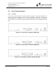
2.3.2 Test Points / Power Indicator
ON This is an LED indication. When lit GREEN, the LYNX.sc is powered.
The LYNX.sc radio products do not have an on/off switch.
GND This is a test point referenced to chassis ground. This is used in conjunction with the
next two test points to measure voltages related to radio performance.
RSL This is a test point which relates to the Received Signal Level (RSL). A voltage can be
measured with a voltmeter (using the GND test point for reference) which corresponds
to the actual power level of the incoming received signal. While the DISPLAY FAR
END button is pressed, this RSL voltage corresponds to the RSL of the far-end radio.
These measurements are used during installation, maintenance and troubleshooting.
LOCAL TX
PWR
This is a test point which corresponds to the output transmit power of the radio. A
voltage can be measured with a voltmeter (using the GND test point for reference)
which corresponds to the actual power level of the outgoing signal. This measurement
is used during installation, maintenance and troubleshooting
. This voltage only applies to the near-end and does not allow measurement of
the far-end output transmit power, even when the DISPLAY FAR END button
is pressed.
There is a receptacle on the front panel to the right of the LOCAL TX PWR test point
which is an installation adjustment allowing the output transmit power to be increased
or decreased within the radio's specified limits. Using a small screwdriver, this
adjustment is used to set the output power of the transmitter, in accordance to the
path planning.
The LYNX.sc systems requires professional installation. Transmitted output
power limits may apply when using this radio. Consult FCC, IC, ETSI Western
Multiplex or other regulatory authorities for limits which may apply. See
Section 3.13.1 for details on setting output power.