
User's Manual


INSTALLATION AND MAINTENANCE MANUAL
LYNX.sc E1 FAMILY
SPREAD SPECTRUM RADIOS
SEPTEMBER 1999
PAGE 5-4 SECTION 5: APPENDICES
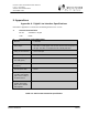
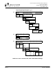
Shaded switch positions are factory default
1 2 3 4 5 6 7 8
SW1 1
0 0 x 0 0 0 0 0 0
1 2 Loss of Input Data Alarm
0 0 Enable (depends on model)
1 1 Disable
3 Loopback Test Source
0 Internal
1 External
4 Error LED Latch
0 Enable
1 Disable (Flash)
5 Rx AIS Output
0 Enable
1 Disable
Diagnostics Port 7
TBOS 0
Craft 1
Aux Data Port 8
Bridged (TBOS) 0
Enabled (Clear) 1
1 2 3 4
SW2 1
0 0 0 0 0
1 CEPT-1 Ground Note:
0 Floating Not used
1 Grounded on 2E/4E
1 2 3 4 5 6 7 8
SW3 1 x x
0 0 0 x x 0 0 x x
1 2 Spreading Code
0 0 Code 1
0 1 Code 2
1 0 Code 3
1 1 Code 4
3 4 Loss of Input Data Alarm
0 0 Enable (depends on model)
1 1 Disable
Frequency
Xmtr Rcvr 7 8
A1 2410 2453 0 0
A2 2453 2410 0 1
B1 2430 2473 1 0
B2 2473 2430 1 1
Table B-1: LYNX.sc 2.4 GHz 1xE1, 2xE1 & 4XE1 Switch Settings