
User's Manual


INSTALLATION AND MAINTENANCE MANUAL
LYNX.sc E1 FAMILY
SPREAD SPECTRUM RADIOS
SEPTEMBER 1999
PAGE 4-22 SECTION 4: TROUBLESHOOTING
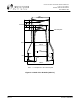
4.9 Back-to-Back Testing
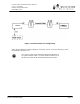
Back-to-back testing, as shown in Figure 4-1, is an ideal method of testing the LYNX.sc radios.
This testing eliminates link problems caused by auxiliary equipment, installation, or the radio path
and isolates potential radio hardware problems. Back-to-back testing must be performed with both
radios at the same location. The following test equipment is required:
v DC power source capable of supplying approximately 90 Watts (total) to the radios (or
two AC adapters)
v One low-loss coaxial cable, N-to-N male
v One (or more) coaxial in-line calibrated fixed attenuators, 40 to 80 dB total attenuation
The following test equipment may also be useful to perform further testing of the LYNX.sc radio:
v BER tester
v Variable (60 dB range or more) RF attenuator (rated for the proper frequency, 2.4 or 5.8
GHz)
v RF power meter
Back-to-back testing must be performed to verify a radio
problem before returning any radio to the factory for repair.
When the equipment is connected as shown in Figure 4-1, without connecting the BER tester, both
LYNX.sc radios should have no alarm conditions, except for DATA LOSS. When Loopback is
enabled at either end, no errors should be registered by the ERROR indication. If these conditions
have been met, then it is likely that the LYNX.sc radio is operating in accordance to specifications.
If errors or alarms occur during this test, verify that all DIP switch settings are properly set. If alarms
or errors are still present, the radio is likely to be faulty.
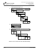
If further troubleshooting is required for the radios themselves, a BER tester can be inserted into the
rear panel bantam jacks (or the appropriate input/output data port) so an end-to-end or loopback
test can be performed to assure that no errors are present in the radio link. In addition, a variable RF
attenuator can be inserted between the radios to fade down the path to determine that the threshold
specification is being met. The BER and threshold tests can be run in both directions to isolate the
radio problem (if any). More information on BER testing is provided in Section 4.10. An RF power
meter can be used to individually test each radio’s output power.