ORiNOCO AP-4000, AP-4000M and AP-4900M User Guide
AP-4000/4000M/4900M User Guide IMPORTANT! Proxim recommends you to visit the Proxim Support site at http:// support.proxim.com for Regulatory Information and latest product updates. Copyright © 2009 Proxim Wireless Corporation. All rights reserved. Covered by one or more of the following U.S. patents: 5,231,634; 5,875,179; 6,006,090; 5,809,060; 6,075,812; 5,077,753. This User Guide and the software described in it are copyrighted with all rights reserved.
AP-4000/4000M/4900M User Guide Contents 1 Introduction . . . . . . . . . . . . . . . . . . . . . . . . . . . . . . . . . . . . . . . . . . . . . . . . . . . . . . . . . . . . . . . . . . 9 Products Covered in this User Guide . . . . . . . . . . . . . . . . . . . . . . . . . . . . . . . . . . . . . . . . . . . . . . . . . . . . . . 9 Introduction to Wireless Networking . . . . . . . . . . . . . . . . . . . . . . . . . . . . . . . . . . . . . . . . . . . . . . . . . . . . . . . 9 Mesh Networking . . . . . .
AP-4000/4000M/4900M User Guide System . . . . . . . . . . . . . . . . . . . . . . . . . . . . . . . . . . . . . . . . . . . . . . . . . . . . . . . . . . . . . . . . . . . . . . . . . . . . 45 Dynamic DNS Support . . . . . . . . . . . . . . . . . . . . . . . . . . . . . . . . . . . . . . . . . . . . . . . . . . . . . . . . . . . . . . . . . . . . . . 46 Network . . . . . . . . . . . . . . . . . . . . . . . . . . . . . . . . . . . . . . . . . . . . . . . . . . . . . . . . . . . . . . . . . . . . . . . . .
AP-4000/4000M/4900M User Guide Radius Profiles . . . . . . . . . . . . . . . . . . . . . . . . . . . . . . . . . . . . . . . . . . . . . . . . . . . . . . . . . . . . . . . . . . . . . 125 RADIUS Servers per Authentication Mode and per VLAN. . . . . . . . . . . . . . . . . . . . . . . . . . . . . . . . . . . . . . . . . . 125 Configuring Radius Profiles . . . . . . . . . . . . . . . . . . . . . . . . . . . . . . . . . . . . . . . . . . . . . . . . . . . . . . . . . . . . . . . . .
AP-4000/4000M/4900M User Guide Retrieve File . . . . . . . . . . . . . . . . . . . . . . . . . . . . . . . . . . . . . . . . . . . . . . . . . . . . . . . . . . . . . . . . . . . . . . . 171 Retrieve File via TFTP . . . . . . . . . . . . . . . . . . . . . . . . . . . . . . . . . . . . . . . . . . . . . . . . . . . . . . . . . . . . . . . . . . . . . 171 Retrieve File via HTTP . . . . . . . . . . . . . . . . . . . . . . . . . . . . . . . . . . . . . . . . . . . . . . . . . . . . . . . . . . . . . . . . . .
AP-4000/4000M/4900M User Guide Log into the AP using HyperTerminal. . . . . . . . . . . . . . . . . . . . . . . . . . . . . . . . . . . . . . . . . . . . . . . . . . . . . . . . . . 204 Log into the AP using Telnet . . . . . . . . . . . . . . . . . . . . . . . . . . . . . . . . . . . . . . . . . . . . . . . . . . . . . . . . . . . . . . . . 204 Set Basic Configuration Parameters using CLI Commands . . . . . . . . . . . . . . . . . . . . . . . . . . . . . . . . . . . . . . . . 205 Other Network Settings . .
AP-4000/4000M/4900M User Guide Support Options . . . . . . . . . . . . . . . . . . . . . . . . . . . . . . . . . . . . . . . . . . . . . . . . . . . . . . . . . . . . . . . . . . . . 270 Proxim eService Web Site Support . . . . . . . . . . . . . . . . . . . . . . . . . . . . . . . . . . . . . . . . . . . . . . . . . . . . . . . . . . . 270 Telephone Support . . . . . . . . . . . . . . . . . . . . . . . . . . . . . . . . . . . . . . . . . . . . . . . . . . . . . . . . . . . . . . . . . . . . . . . .
AP-4000/4000M/4900M User Guide 1 Introduction This chapter contains information on the following: • Products Covered in this User Guide • Introduction to Wireless Networking • Mesh Networking • Guidelines for Roaming • Management and Monitoring Capabilities Products Covered in this User Guide This User Guide details functionality of the following products: Product AP-4000 AP-4000M AP-49000M Description Tri-mode AP that supports: • 802.11b, 802.11g, and 802.
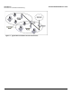
Introduction Introduction to Wireless Networking AP-4000/4000M/4900M User Guide Figure 1-1 Typical Wireless Network Access Infrastructure 10
Introduction Mesh Networking AP-4000/4000M/4900M User Guide Mesh Networking Using the ORiNOCO Mesh Creation Protocol (OMCP), the AP-4000/4000M/4900M supports structured Mesh networking. In a Mesh network, access points use their wireless interface as a backhaul to the rest of the network.
Introduction Mesh Networking AP-4000/4000M/4900M User Guide are discovered, MAP2 through MAP8 will build a neighbor table from the beacons and probe responses they receive. The neighbor table contains three kinds of links: • Active: Link with a Mesh neighbor that has gone through association and authentication, and the port is open. • Connected: Link with a Mesh neighbor that has gone through association and authentication, but the port is closed.
Introduction Mesh Networking AP-4000/4000M/4900M User Guide After a short while, the network in this example will look like Figure 1-4, where solid lines indicate active Mesh links and dotted lines indicate established but inactive Mesh links. Figure 1-4 Mesh Startup Topology Example – Step 3 In this example, if MAP8 loses the Mesh link to MP9, MAP8 will immediately activate the Mesh link to MAP7.
Introduction Guidelines for Roaming – AP-4000/4000M/4900M User Guide Average utilization (time that a client is actually transferring data) is 10%. If the conditions on your network are different than the assumptions above, then the maximum number of APs should be adjusted accordingly. NOTE: Clients whose traffic must traverse multiple hops in order to reach the portal will have lower throughput than clients whose traffic traverses fewer hops.
Introduction Management and Monitoring Capabilities • HTTP/HTTPS Interface • Command Line Interface • SNMP Management • SSH (Secure Shell) Management AP-4000/4000M/4900M User Guide HTTP/HTTPS Interface The HTTP Interface (Web browser Interface) provides easy access to configuration settings and network statistics from any computer on the network. You can access the HTTP Interface over your LAN (switch, hub, etc.
Introduction Management and Monitoring Capabilities AP-4000/4000M/4900M User Guide Enterprise MIB for more information; the MIB can be opened with any text editor, such as Microsoft Word, Notepad, or WordPad. SNMPv3 Secure Management SNMPv3 is based on the existing SNMP framework, but addresses security requirements for device and network management.
AP-4000/4000M/4900M User Guide Installation and Initialization 2 In this chapter: • • AP-4000/4000M/4900M Hardware Description – Overview – LED Indicators – Power-over-Ethernet (PoE) – Antennas Prerequisites – General Prerequisites – Mesh Prerequisites – PXU (ProximUnify) Prerequisites • System Requirements • Product Package • Hardware Installation • – Attach Cables – Install the Security Cover (Optional) – Mount the AP-4000/4000M/4900M – Power On the Unit – Install Extern
Installation and Initialization AP-4000/4000M/4900M Hardware Description AP-4000/4000M/4900M User Guide AP-4000/4000M/4900M Hardware Description Overview The AP-4000 and AP-4000M are tri-mode APs equipped with the following embedded radios: • One embedded 802.11a radio and one embedded 802.11b/g radio, enabling simultaneous support of 802.11a, 802.11b, and 802.11g clients as well as Mesh operation on either the 2.4 or 5 GHz band.
Installation and Initialization AP-4000/4000M/4900M Hardware Description Ethernet Wireless Interfaces AP-4000/4000M/4900M User Guide Power Figure 2-2 LED Indicators on the Top Panel Power-over-Ethernet (PoE) The AP-4000/4000M/4900M is equipped with an 802.3af-compliant Power-over-Ethernet (PoE) module. PoE delivers both data and power to the access point over a single Ethernet cable. If you choose to use PoE, there is no difference in operation; the only difference is in the power source.
Installation and Initialization AP-4000/4000M/4900M Hardware Description AP-4000/4000M/4900M User Guide External Antennas The AP-4000/4000M/4900M also has four antenna connectors, two on each radio, for use with external antennas.External antennas can be used with either radio on the AP-4000/4000M/4900M. NOTE: All AP-4900M units, and AP-4000/4000M units using external antennas, must be installed by a suitably trained professional installation technician or by a qualified installation service.
Installation and Initialization AP-4000/4000M/4900M Hardware Description AP-4000/4000M/4900M User Guide 4.9 GHz Antenna On the AP-4900M, antenna connector 3 is equipped with a pigtail adaptor for connection to a 4.9 GHz antenna. When the AP-4900M is configured to operate in the 4.9 GHz Public Safety operational mode, antenna diversity is automatically disabled by default, and antenna 3 is configured for use. Connecting an external antenna to this antenna port disables the corresponding internal antenna.
Installation and Initialization Prerequisites AP-4000/4000M/4900M User Guide Prerequisites General Prerequisites Before installing your unit, you need to gather certain network information. The following table identifies the information you need. Parameter Description Network Name (SSID of the wireless cards) You must assign the Access Point a Network Name before wireless users can communicate with it. The clients also need the same Network Name.
Installation and Initialization System Requirements AP-4000/4000M/4900M User Guide Mesh Prerequisites Before setting up a Mesh network, gather the following information: Parameter Description Mesh Mode The mode in which the AP will be used. If the AP will be connected directly to the wired backbone, it should be configured for Mesh Portal mode; if it will connect to the Portal and backbone wirelessly, it should be configured for Mesh AP mode.
Installation and Initialization Product Package AP-4000/4000M/4900M User Guide Product Package Each AP-4000/4000M/4900M shipment includes the items in the following table. Verify that you have received all parts of the shipment. NOTE: Unless noted in this table, cables are not supplied with the unit.
Installation and Initialization Hardware Installation AP-4000/4000M/4900M User Guide Hardware Installation NOTE: All AP-4900M units, and AP-4000/4000M units using external antennas, must be installed by a suitably trained professional installation technician or by a qualified installation service. NOTE: Before installing and using this product, visit the Proxim Support site at http://support.proxim.com for Regulatory Information.
Installation and Initialization Hardware Installation AP-4000/4000M/4900M User Guide • Use a straight-through Ethernet cable if you intend to connect the unit to a switch, hub, or patch panel. • Use a cross-over Ethernet cable or adapter if you intend to connect the unit to a single computer. Figure 2-4 Cabling without PoE 3. Optionally, connect an RS-232 cable (not shown) to the RS-232 console port (the right port, labeled “RS-232”).
Installation and Initialization Hardware Installation AP-4000/4000M/4900M User Guide Install the Security Cover (Optional) You can optionally install a security cover to deter unauthorized access to the unit. The security cover is a plastic enclosure that prevents access to the cabling and the Reset and Reload buttons. 1.
Installation and Initialization Hardware Installation AP-4000/4000M/4900M User Guide Wall Mounting Follow these steps to mount the unit on a wall: 1. If the unit’s power supply is plugged in, unplug it. 2. Put the mounting plate up to the wall so that the embossed letter “L” is on top (see figure). If the plate is correctly oriented, the circular tab that is vertically aligned with the square hole should be on top. 3. Fasten the mounting plate with two screws through the circular holes of the plate.
Installation and Initialization Hardware Installation AP-4000/4000M/4900M User Guide 2. Screw through the mounting plate. 3. Place the AP up against the mounting plate. Orient the AP with the long access vertical, with the connectors facing right. Power On the Unit The AP can be powered by a power supply (just plug the power cord of the power supply into an AC power outlet), or by Power-over-Ethernet (connect a PoE DC injector to the Ethernet cable).
Installation and Initialization Hardware Installation AP-4000/4000M/4900M User Guide NOTE: AP-4000 models 8670-US2 and 8670-AU do not provide external antenna connectors for 5 GHz (802.11a) operation. Figure 2-8 Opening the Antenna Compartment 2. There are four antenna connectors in the AP-4000/4000M/4900M, labeled 1 through 4. Connectors 1 and 2 are for the 802.11b/g radio, and connectors 3 and 4 and for the 802.11a/4.9 GHz radio.
Installation and Initialization Hardware Installation AP-4000/4000M/4900M User Guide Connecting Antenna(s) to the AP-4900M for 4.9 GHz Operation To attach an external antenna to the AP-4900M, attach the selected antenna to the pigtail attachment connected to the AP’s antenna connector 3 (see Figure 2-10). For a list of recommended antennas, see http://www.proxim.com/products/wifi/accessories.
Installation and Initialization Hardware Installation AP-4000/4000M/4900M User Guide Antenna Types and Maximum Gain For devices using external antennas, professional installers should select only the antenna types listed in the following table, with gain not exceeding the listed maximum gain for each type. Frequency Band 2.4 GHz 5 GHz 4.9 GHZ Antenna Type Omni Panel Yagi Parabolic Omni Panel Sector Parabolic No restriction Maximum Gain 10 14 14 24 13 28.2 17 33.4 No restriction beyond EIRP compliance.
Installation and Initialization Initialization AP-4000/4000M/4900M User Guide Initialization The following sections detail how to initialize the AP using ScanTool, log in to the HTTP interface, perform an initial configuration of the AP using the Setup Wizard, and download the required AP software. • Using ScanTool • Logging In • Using the Setup Wizard • Installing the Software Using ScanTool ScanTool is a software utility that is included on the installation CD-ROM.
Installation and Initialization Initialization AP-4000/4000M/4900M User Guide NOTE: If your Access Point does not appear in the Scan List, click the Rescan button to update the display. If the unit still does not appear in the list, see Troubleshooting for suggestions. Note that after rebooting an Access Point, it may take up to five minutes for the unit to appear in the Scan List. 4. Do one of the following: • If the AP has been assigned an IP address by a DHCP server on the network: a.
Installation and Initialization Initialization AP-4000/4000M/4900M User Guide k. Click the Change button to return to the Change screen. l. Click the Web Configuration button at the bottom of the Change screen. m. Proceed to the Logging In section for information on how to access the HTTP interface using this IP address. Logging In Once the AP has a valid IP Address and an Ethernet connection, you may use your web browser to monitor and configure the AP.
Installation and Initialization Initialization AP-4000/4000M/4900M User Guide Figure 2-14 System Status Screen The buttons on the left of the screen provide access to the monitoring and configuration options for the AP. See Advanced Configuration to begin configuring the AP manually. You can also exit the Web interface or reboot the AP using these buttons. The Command Line Interface (CLI) also provides a method for monitoring and configuring the AP using Telnet or a serial connection.
Installation and Initialization Initialization AP-4000/4000M/4900M User Guide • Save & Next Button: Each Setup Wizard screen has a Save & Next button. Click this button to submit any changes you made to the unit’s parameters and continue to the next page. The instructions below describe how to navigate the Setup Wizard using the Save & Next buttons. • Navigation Panel: The Setup Wizard provides a navigation panel on the left-hand side of the screen.
Installation and Initialization Initialization AP-4000/4000M/4900M User Guide — Primary Network Name (SSID): Enter a Network Name (between 1 and 32 characters long) for the wireless network. You must configure each wireless client to use this name as well. Note that the unit supports up to 16 SSIDs/VLANs per wireless interface. Please see the Advanced Configuration chapter for information on the detailed rules on configuring multiple SSIDs, VLANs, and security profiles.
Installation and Initialization Initialization AP-4000/4000M/4900M User Guide Download the Software 1. In your web browser, go to http://support.proxim.com. 2. If prompted, create an account to gain access. NOTE: The Knowledgebase is available to all website visitors. First-time users will be asked to create an account to gain access. 3. Click Search Knowledgebase. 4. In the Search Knowledgebase field, enter one of the following: • For the AP-4000: 1250. • For the AP-4000M: 1934.
Installation and Initialization Initialization AP-4000/4000M/4900M User Guide Figure 2-17 Warning Message 5. Click OK to continue with the operation or Cancel to abort the operation. 6. If the operation is unsuccessful, you will receive an error message. If this occurs, see the Troubleshooting chapter or attempt installing the software with a TFTP server, as described in the next section. If the operation is successful, you will receive a confirmation message. 7.
Installation and Initialization Initialization AP-4000/4000M/4900M User Guide 4. Enter the IP address of your TFTP server in the field provided. 5. Enter the File Name (including the file extension). If the file is located in the default TFTP directory, you need enter only the file name. Otherwise, enter the full directory path and file name. 6. Select the File Type from the drop-down menu (use Img for software updates). 7. Select Download & Reboot from the File Operation drop-down menu. 8. Click OK.
AP-4000/4000M/4900M User Guide System Status 3 The first screen displayed after Logging In is the System Status screen. You can always return to this screen by clicking the Status button. Figure 3-1 System Status Screen The System Status screen provides the following information: • System Status: This area provides system-level information, including the unit’s IP address and contact information. See System for information on these settings. • System Alarms: System traps (if any) appear in this area.
AP-4000/4000M/4900M User Guide Advanced Configuration 4 This chapter contains information on configuring settings in the following categories: • System: Configure specific system information such as system name and contact information. • Network: Configure IP, DNS client, DHCP server, DHCP Relay Agent, DHCP Relay Servers, Link Integrity, and SNTP settings. • Interfaces: Configure the Access Point’s interfaces: Wireless A, Wireless B, Ethernet, and Mesh.
Advanced Configuration AP-4000/4000M/4900M User Guide Figure 4-1 Configure Main Screen 2. Click the tab that corresponds to the parameter you want to configure. For example, click Network to configure the Access Point’s TCP/IP settings. Each Configure tab is described in the remainder of this chapter.
Advanced Configuration System AP-4000/4000M/4900M User Guide System You can configure and view the following parameters within the System Configuration screen: • Name: The name assigned to the AP. See the Dynamic DNS Support and Access Point System Naming Convention sections for rules on naming the AP. • Country: The country in which the AP will be used. Note that some countries have two selectable options (one for indoor use and one for outdoor use).
Advanced Configuration System AP-4000/4000M/4900M User Guide Figure 4-2 System Tab Dynamic DNS Support DNS is a distributed database mapping the user readable names and IP addresses (and more) of every registered system on the Internet. Dynamic DNS is a lightweight mechanism which allows for modification of the DNS data of host systems whose IP addresses change dynamically.
Advanced Configuration Network AP-4000/4000M/4900M User Guide Network The Network tab contains the following sub-tabs: • IP Configuration • DHCP Server • DHCP Relay Agent • Link Integrity • SNTP (Simple Network Time Protocol) IP Configuration This tab is used to configure the internet (TCP/IP) settings for the access point. These settings can be either entered manually (static IP address, subnet mask, and gateway IP address) or obtained automatically (dynamic).
Advanced Configuration Network AP-4000/4000M/4900M User Guide • IP Address: The Access Point’s IP address. When IP Address Assignment Type is set to Dynamic, this field is read-only and reports the unit’s current IP address. The Access Point will default to 169.254.128.132 if it cannot obtain an address from a DHCP server. Though the Access Point starts functioning with the default IP address, it will continue to renew as a DHCP address and will get one if DHCP server is available.
Advanced Configuration Network AP-4000/4000M/4900M User Guide Figure 4-4 DHCP Server Configuration Screen You can configure and view the following parameters within the DHCP Server Configuration screen: NOTE: You must reboot the AP before changes to any of these DHCP server parameters take effect. • Enable DHCP Server: Place a check mark in the box provided to enable DHCP Server functionality.
Advanced Configuration Network AP-4000/4000M/4900M User Guide NOTE: The Default Lease Time cannot be larger than the Maximum Lease Time. If you set the Maximum Lease Time, you should also set the Default Lease Time to ensure that the Default Lease Time is less than the Maximum. – Comment (optional) – Status: IP Pools are enabled upon entry in the table. You can also disable or delete entries by changing this field’s value.
Advanced Configuration Network AP-4000/4000M/4900M User Guide To add entries to the table of DHCP Relay Agents, click Add in the DHCP Server IP Address Table; to edit existing entries, click Edit. The following window is displayed. Figure 4-6 DHCP Server IP Address Table - Edit Entries To add an entry, enter the IP Address of the DHCP Server and a comment (optional), and click OK. To edit an entry, make changes to the appropriate entry.
Advanced Configuration Network AP-4000/4000M/4900M User Guide Figure 4-7 Link Integrity Configuration Screen SNTP (Simple Network Time Protocol) SNTP allows a network entity to communicate with time servers in the network/internet to retrieve and synchronize time of day information. When this feature is enabled, the AP will attempt to retrieve the time of day information from the configured time servers (primary or secondary), and, if successful, will update the relevant time objects in the AP.
Advanced Configuration Network AP-4000/4000M/4900M User Guide Figure 4-8 SNTP Configuration Screen You can configure and view the following parameters within the SNTP screen: • SNTP Status: Select Enable or Disable from the drop-down menu. The selected status will determine which of the parameters on the SNTP screen are configurable. NOTE: When SNTP is enabled, it will take some time for the AP to retrieve the time of day from the configured time servers and update the relevant date and time parameters.
Advanced Configuration Interfaces AP-4000/4000M/4900M User Guide Interfaces From the Interfaces tab, you configure the Access Point’s operational mode settings, power control settings, wireless interface settings and Ethernet settings. You may also configure a Wireless Distribution System for AP-to-AP communications. The Interfaces tab contains the following sub-tabs: • Operational Mode • Wireless-A (802.11a/4.9 GHz Radio) and Wireless-B (802.
Advanced Configuration Interfaces AP-4000/4000M/4900M User Guide Figure 4-10 Operational Mode Screen (AP-4900M) The Wireless-A interface operates in 802.11a mode on the AP-4000/4000M and in either 802.11a mode or 4.9 GHz Public Safety mode on the AP-4900M. In 4.9 GHz Public Safety mode, you must also select a Channel Bandwidth. This option is not configurable in the AP-4000/4000M. See Available Channels for a list of channels available with each bandwidth.
Advanced Configuration Interfaces AP-4000/4000M/4900M User Guide Enable H Band Support In compliance with FCC regulations, Dynamic Frequency Selection is required in the middle frequency band (M band: 5.26 GHz - 5.32 Ghz) and high frequency band (H band: 5.470 GHz - 5.725 GHz). DFS is enabled automatically when you use one or both of these frequency bands.
Advanced Configuration Interfaces AP-4000/4000M/4900M User Guide The beacon frame contains information on the country code, the maximum allowable transmit power, and the channels to be used for the regulatory domain. The same information is transmitted in probe response frames in response to a client’s probe requests. Once the client has acquired the information required to meet the transmit requirements of the regulatory domain, it configures itself for operation in the regulatory domain.
Advanced Configuration Interfaces AP-4000/4000M/4900M User Guide 3. Enter the desired backoff from the maximum Transmit Power level (between 0 and 35 dBm) in the Wireless-A: Transmit Power Level Back-Off or Wireless-B: Transmit Power Level Back-Off field. 4. Click OK.
Advanced Configuration Interfaces AP-4000/4000M/4900M User Guide Wireless-A (802.11a/4.9 GHz Radio) and Wireless-B (802.
Advanced Configuration Interfaces AP-4000/4000M/4900M User Guide You can view and configure the following parameters for the Wireless-A and Wireless-B interfaces: NOTE: You must reboot the Access Point before any changes to these parameters take effect. • Physical Interface Type: For Wireless Interface A on the AP-4000/4000M, this field reports “802.11a (OFDM 5 GHz).” On the AP-4900M, this field reports “802.11a (OFDM 5 GHz)” when operating in 802.11a mode, and “Public Safety (OFDM 4.
Advanced Configuration Interfaces AP-4000/4000M/4900M User Guide – For 802.11b/g -- Auto Fallback, 1, 2, 5.5, 6, 9, 11, 12, 18, 24, 36, 48, 54 Mbits/sec – For 802.11g-wifi -- Auto Fallback, 1, 2, 5.5, 6, 9, 11, 12, 18, 24, 36, 48, 54 Mbits/sec NOTE: 802.11g-wifi has been defined for Wi-Fi testing purposes. It is not recommended for use in your wireless network environment. NOTE: Turbo mode is supported in only in 802.11a mode in the FCC regulatory domain when DFS is not required.
Advanced Configuration Interfaces AP-4000/4000M/4900M User Guide In shutdown state, AP will not transmit and receive frames from the wireless interface and will stop transmitting periodic beacons. Moreover, none of the frames received from the Ethernet interface will be forwarded to that wireless interface. Wireless service on a wireless interface of the AP can be resumed through CLI/HTTP/SNMP management interface.
Advanced Configuration Interfaces AP-4000/4000M/4900M User Guide Figure 4-12 Channel Blacklist Table 3. Click Edit in the Channel Blacklist Table 4. Set Blacklist Status to Enable. Figure 4-13 Channel Blacklist Table - Edit Screen • Wireless Distribution System: A Wireless Distribution system can be used to establish point-to-point (i.e. wireless backhaul) connections with other access points. See Wireless Distribution System (WDS) for configuration information.
Advanced Configuration Interfaces AP-4000/4000M/4900M User Guide the background and triggers ACS to perform an Auto Scan Function to select the channel with lowest interference and dynamically switches to the new channel. The DCS is triggered under the following conditions: 1. Dynamic channel change required (Radar Detection and Configuration change) 2.
Advanced Configuration Interfaces AP-4000/4000M/4900M User Guide Figure 4-15 A complete Interfaces page 65
Advanced Configuration Interfaces AP-4000/4000M/4900M User Guide DCS can be configured using the following interfaces: • • • Web (HTTP) Interface Command Line Interface (CLI) MIB (SNMP) Requirements Web (HTTP) Interface The HTTP Interface (Web browser Interface) provides easy access to configuration settings and network statistics from any computer on the network. You can access the HTTP Interface over your LAN (switch, hub, etc.
Advanced Configuration Interfaces AP-4000/4000M/4900M User Guide Command Line Interface (CLI) See the Command Line Interface (CLI) section in Appendix A. MIB (SNMP) Requirements DCS feature can be managed and monitored by MIB objects too. All the configuration parameters are present for both Interface A and Interface B separately. The oriWirelessIfDCSThreshold object stores the DCS Threshold from 1 to 10. See the table below for defaults and units for all objects.
Advanced Configuration Interfaces AP-4000/4000M/4900M User Guide • You cannot manually select the device’s operating channel; you must let the unit select the channel. You may make channels unavailable by manually “blacklisting” them and preventing those channels being selected, in accordance with local regulations or interference. You can also display the Channel Blacklist Table to view the channels that have been blacklisted by the AP.
Advanced Configuration Interfaces AP-4000/4000M/4900M User Guide Transparent Mode Transparent mode is the default mode and is equivalent to the NO VLAN support. The VLAN receievs both the tagged and untagged frames from the network. Transparent mode simply forwards both the tagged and untagged frames received on the Ethernet port to WDS, Mesh or BSS and is not able to read any VLAN information.
Advanced Configuration Interfaces AP-4000/4000M/4900M User Guide Trunk Mode Trunk mode works as a filter. Trunk links provide VLAN identification for frames travelling between switches. Once this mode is enabled, the frames received from the WDS, Mesh or wireless ports are filtered and compared with the trunk tables entries. The device percolates the incoming frames comparing with the trunk table data and forwards to the respective ports. The trunk table is configurable on the Access Point.
Advanced Configuration Interfaces AP-4000/4000M/4900M User Guide Management VLAN Configuration Trunk Mode: In trunk mode if any management VLAN ID is configured then that management VLAN ID should present in trunk table, then only we can able to manage the device. Access Mode : In Access mode if any management VLAN ID is configured then that management VLAN ID should be same as Access VLAN ID, then only we can able to manage the device .
Advanced Configuration Interfaces AP-4000/4000M/4900M User Guide Web Interface The HTTP Interface (Web browser Interface) provides easy access to configuration settings and network statistics from any computer on the network. You can access the HTTP Interface over your LAN (switch, hub, etc.), over the Internet, or with a “crossover” Ethernet cable connected directly to your computer’s EthernetPort.
Advanced Configuration Interfaces AP-4000/4000M/4900M User Guide • When VLAN Mode is Access, text boxes Access VLAN ID and Access VLAN Priority are enabled and VLAN 1 to VLAN 16 text boxes are disabled. • When VLAN Mode is Mixed, all the text boxes from VLAN 1 to VLAN 16, Access VLAN ID and Access VLAN Priority are enabled. Select your mode manually and configure the parameters and finally click OK. Command Line Interface (CLI) See the Command Line Interface (CLI) section in Appendix A.
Advanced Configuration Interfaces AP-4000/4000M/4900M User Guide In the WDS example below, AP 1 and AP 2 communicate over a WDS link (represented by the blue line). This link provides Client 2 with access to network resources even though AP 2 is not directly connected to the Ethernet network. Packets destined for or sent by the client are relayed between the Access Points over the WDS link. Figure 4-19 WDS Example Bridging WDS Each WDS link is mapped to a logical WDS port on the AP.
Advanced Configuration Interfaces AP-4000/4000M/4900M User Guide WDS Setup Procedure NOTE: You must disable Auto Channel Select to create a WDS. Each Access Point that is a member of the WDS must have the same channel setting to communicate with each other. NOTE: WDS and Mesh functionality cannot be enabled on the same radio when the AP is configured to function as a Mesh AP. To setup a wireless backbone follow the steps below for each AP that you wish to include in the Wireless Distribution System. 1.
Advanced Configuration Interfaces AP-4000/4000M/4900M User Guide Figure 4-21 Adding WDS Links 6. Select which encryption method to use (if any) from the WDS Security Mode drop-down menu. 7. If you selected a WDS Security Mode, do one of the following: • If you selected WEP: Enter an encryption key. • If you selected AES: Enter a shared secret. 8. Enter the MAC Address that you wrote down in Step 2 in one of the Partner MAC Address field of the Wireless Distribution Setup window. 9.
Advanced Configuration Interfaces AP-4000/4000M/4900M User Guide Ethernet Select the desired speed and transmission mode from the drop-down menu. Half-duplex means that only one side can transmit at a time and full-duplex allows both sides to transmit. When set to auto-duplex, the AP negotiates with its switch or hub to automatically select the highest throughput option supported by both sides.
Advanced Configuration Interfaces AP-4000/4000M/4900M User Guide Mesh Mesh functionality can be enabled on only one of the AP’s wireless interfaces. When configured for Mesh, the AP’s wireless interface simultaneously functions as a Mesh link and as a radio to service clients. CAUTION: Mesh mis-configuration may cause problems in your wireless network. Before configuring an interface for Mesh functionality, see Mesh Network Configuration. NOTE: AP-4000 units must use software version 3.
Advanced Configuration Interfaces AP-4000/4000M/4900M User Guide • Security Mode: Select None to use Mesh networking without security, or AES to enable AES encryption between Mesh links. • Shared Secret: Enter a password between 6 and 32 characters. This is the password shared between a Mesh AP and the Portal to which it is connected when AES is selected as the security mode. • Mesh Mobility: Set this parameter to Fixed if the AP is statically placed, or to Mobile if the AP is mobile.
Advanced Configuration Interfaces AP-4000/4000M/4900M User Guide Mesh Link Parameters To reset these parameters to their default settings, click the Default button. NOTE: Changes to these parameters require a reboot in order to take effect. • Maximum Active Mesh Links: Select a number between 1 and 32 to configure the number of Mesh links that can be connected to a single Mesh portal or Mesh AP, as follows: – Mesh Portal: This number represents the maximum downlinks to Mesh APs (up to 32).
Advanced Configuration Interfaces AP-4000/4000M/4900M User Guide • Disable Client Access on No Uplink Connection: When this option is enabled, the AP will not provide wireless connections to clients on both radios if the unit does not have an uplink connection. • Notify Clients on Uplink Change: When this option is enabled, the AP will send a deauthentication message to currently connected clients when its uplink changes.
Advanced Configuration Management AP-4000/4000M/4900M User Guide Management The Management tab contains the following sub-tabs: • Passwords • IP Access Table • Services • Automatic Configuration (AutoConfig) • Hardware Configuration Reset (CHRD) Passwords Passwords are stored in flash memory and secured using encryption. You can configure the following passwords: • SNMP Read Community Password: The password for read access to the AP using SNMP.
Advanced Configuration Management AP-4000/4000M/4900M User Guide Figure 4-25 Management-Password Page IP Access Table The Management IP Access table limits in-band management access to the IP addresses or range of IP addresses specified in the table. This feature applies to all management services (SNMP, HTTP, and CLI) except for CLI management over the serial port. To configure this table, click Add and set the following parameters: • IP Address: Enter the IP Address for the management station.
Advanced Configuration Management • AP-4000/4000M/4900M User Guide Secure Management Status: Enables the further configuration of HTTPS Access, SNMPv3, and Secure Shell (SSH). After enabling Secure Management, you can choose to configure HTTPS (SSL) and Secure Shell access on the Services tab, and to configure SNMPv3 passwords on the Passwords tab.
Advanced Configuration Management AP-4000/4000M/4900M User Guide Figure 4-26 Management Services Configuration Screen 85
Advanced Configuration Management AP-4000/4000M/4900M User Guide Telnet Configuration Settings • Telnet Interface Bitmask: Select the interface (Ethernet, Wireless-Slot A, Wireless-Slot B, All Interfaces) from which you can manage the AP via telnet. This parameter can also be used to Disable telnet management. • Telnet Port Number: The default port number for Telnet applications is 23.
Advanced Configuration Management AP-4000/4000M/4900M User Guide NOTE: When Secure Management is enabled on the AP, SSH will be enabled by default and cannot be disabled. Host keys must either be generated externally and uploaded to the AP (see Uploading Externally Generated Host Keys), generated manually, or auto-generated at the time of SSH initialization if SSH is enabled and no host keys are present. There is no key present in an AP that is in a factory default state.
Advanced Configuration Management AP-4000/4000M/4900M User Guide Serial Configuration Settings The serial port interface on the AP is enabled at all times. See Setting IP Address using Serial Port for information on how to access the CLI interface via the serial port. You can configure and view the following parameters: • Serial Baud Rate: Select the serial port speed (bits per second). Choose between 2400, 4800, 9600, 19200, 38400, or 57600; the default Baud Rate is 9600.
Advanced Configuration Management AP-4000/4000M/4900M User Guide • RADIUS Profile for Management Access Control: Specifies the RADIUS Profile to be used for RADIUS Based Management Access. • Local User Status: Enables or disables the local user when RADIUS Based Management is enabled. The default local user ID is root. • Local User Password and Confirm Password: The default local user password is public.
Advanced Configuration Management AP-4000/4000M/4900M User Guide Figure 4-28 Automatic Configuration Screen Set up Automatic Configuration for Dynamic IP Perform the following procedure to enable and set up Automatic Configuration when you have a dynamic IP address for the TFTP server via DHCP. The Configuration filename and the TFTP server IP address are contained in the DHCP response when the AP gets its IP address dynamically from the DHCP server.
Advanced Configuration Management AP-4000/4000M/4900M User Guide Figure 4-29 DHCP Options: Setting the Boot Server Host Name 4. Add the Boot Server Hostname and Boot Filename parameters to the Available Options list. 5. Set the value of the Boot Server Hostname Parameter to the hostname or IP Address of the TFTP server. For example: 11.0.0.7. Figure 4-30 DHCP Options: Setting the Bootfile Name 6. Set the value of the Bootfile Name parameter to the Configuration filename. For example: AP-Config. 7.
Advanced Configuration Management • AP-4000/4000M/4900M User Guide If secure mode is enabled in the AP, only secure (SSL, SNMPv3, SSH) users can modify the values of the Hardware Configuration Reset Status and the configuration reset password. Configuration Reset via Serial Port During Bootup If hardware configuration reset is disabled, the user gets prompted by a configuration reset option to reset the AP to factory defaults during boot up from the serial interface.
Advanced Configuration Management AP-4000/4000M/4900M User Guide When the correct configuration reset password is entered, the AP gets reset to factory defaults and displays the message “AP has been reset to Factory Default Settings.” The AP continues to boot up. If an incorrect configuration reset password is entered, the AP shows an error message and reprompts the user. If the incorrect password is entered three times in a row, the AP proceeds to boot up.
Advanced Configuration Filtering AP-4000/4000M/4900M User Guide Filtering The Access Point’s Packet Filtering features help control the amount of traffic exchanged between the wired and wireless networks. There are four sub-tabs under the Filtering heading: • Ethernet Protocol • Static MAC • Advanced • TCP/UDP Port Ethernet Protocol The Ethernet Protocol Filter blocks or forwards packets based on the Ethernet protocols they support. Follow these steps to configure the Ethernet Protocol Filter: 1.
Advanced Configuration Filtering AP-4000/4000M/4900M User Guide Figure 4-32 Ethernet Protocol Filter Configuration 3. Configure the Ethernet Protocol Filter Table. This table is pre-populated with existing Ethernet Protocol Filters, however, you may enter additional filters by specifying the appropriate parameters. • To add an entry, click Add, and then specify the Protocol Number and a Protocol Name. – Protocol Number: Enter the protocol number. See http://www.iana.
Advanced Configuration Filtering AP-4000/4000M/4900M User Guide For example, you can set up a Static MAC filter to prevent wireless clients from communicating with a specific server on the Ethernet network. You can also use this filter to block unnecessary multicast packets from being forwarded to the wireless network. NOTE: The Static MAC Filter is an advanced feature. You may find it easier to control wireless traffic via other filtering options, such as Ethernet Protocol Filtering.
Advanced Configuration Filtering • AP-4000/4000M/4900M User Guide To block traffic between a specific wired MAC address and a specific wireless MAC address, configure all four parameters. A maximum of 200 entries can be created in the Static MAC filter table. To create an entry, click Add and enter the appropriate MAC addresses and Masks to setup a filter. The entry is enabled automatically when saved. Figure 4-36 Static MAC Filter Table - Add Entries To edit an entry, click Edit.
Advanced Configuration Filtering AP-4000/4000M/4900M User Guide Result: When a logical “AND” is performed on the Wireless MAC Address and Wireless Mask, the result corresponds to any MAC address beginning with the 00:20:2D prefix. Since Wireless Client 1 and Wireless Client 2 share the same prefix (00:02:2D), traffic between the Wired Server and Wireless Clients 1 and 2 is blocked. Wireless Client 3 can still communicate with the Wired Server since it has a different prefix (00:20:A6).
Advanced Configuration Filtering AP-4000/4000M/4900M User Guide Figure 4-37 Advanced Filter Configuration The following protocols are listed in the Advanced Filter Table: • Deny IPX RIP • Deny IPX SAP • Deny IPX LSP • Deny IP Broadcasts • Deny IP Multicasts The AP can filter these protocols in the wireless-to-Ethernet direction, the Ethernet-to-wireless direction, or in both directions. Click Edit and use the Status field to Enable or Disable the filter.
Advanced Configuration Filtering AP-4000/4000M/4900M User Guide Figure 4-38 Static MAC Filter Table - Edit Entries TCP/UDP Port Port-based filtering enables you to control wireless user access to network services by selectively blocking TCP/UDP protocols through the AP.
Advanced Configuration Filtering AP-4000/4000M/4900M User Guide Figure 4-39 TCP/UDP Port Filter Configuration 2. Click Add under the TCP/UDP Port Filter Table heading. 3. In the TCP/UDP Port Filter Table, enter the Protocol Names to filter. 4. Set the destination Port Number (a value between 1 and 65535) to filter. See the IANA Web site at http://www.iana.org/assignments/port-numbers for a list of assigned port numbers and their descriptions. 5.
Advanced Configuration Filtering AP-4000/4000M/4900M User Guide Figure 4-40 TCP/UDP Port Filter Table - Add Entries Editing TCP/UDP Port Filters 1. Click Edit under the TCP/UDP Port Filter Table heading. 2. Make any changes to the Protocol Name or Port Number for a specific entry, if necessary. 3. In the row that defines the port, set the Status to Enable, Disable, or Delete, as appropriate. 4. Select OK.
Advanced Configuration Alarms AP-4000/4000M/4900M User Guide Alarms The Alarms tab has the following sub-tabs: • Groups • Alarm Host Table • Syslog • Rogue Scan Groups Alarm groups can be enabled or disabled via the Web interface. Place a check mark in the box provided to enable a specific group. Remove the check mark from the box to disable the alarms.
Advanced Configuration Alarms AP-4000/4000M/4900M User Guide Trap Name oriTrapAuthenticationFailure Description Client authentication failure has occurred. Authentication failures can range from: • MAC Access Control table • RADIUS MAC authentication • 802.
Advanced Configuration Alarms Trap Name AP-4000/4000M/4900M User Guide Description Severity Level oriTrapDHCPFailed Response to the DHCP client request not received; device not dynamically assigned an IP address Major oriTrapDNSClientLookupFailure DNS client attempts to resolve a specified hostname (DNS lookup) and a failure occurs because either the DNS server is unreachable or there is an error for the hostname lookup. Trap specifies the hostname that was being resolved.
Advanced Configuration Alarms AP-4000/4000M/4900M User Guide Trap Name Description Severity Level oriTrapInvalidImage Invalid image loaded onto device Major oriTrapImageTooLarge Image loaded on the device exceeds the size limitation of flash Major oriTrapIncompatibleImage Incompatible image loaded onto device Major oriTrapInvalidImageDigitalSignature Image with invalid digital signature is loaded onto device Major SNTP Trap Group Trap Name Description Severity Level oriTrapSNTPFailure S
Advanced Configuration Alarms AP-4000/4000M/4900M User Guide RFC 1215-Trap Trap Name Description Severity Level coldStart AP is on or rebooted Informational linkUp AP's Ethernet interface link is up (working) Informational linkDown AP's Ethernet interface link is down (not working) Informational Bridge MIB (RFC 1493) Alarms Trap Name Description Severity Level New Root AP has become the new root in the Spanning Tree network Informational topologyChange Trap is not sent if a newRoot trap
Advanced Configuration Alarms AP-4000/4000M/4900M User Guide Syslog The Syslog messaging system enables the AP to transmit event messages to a central server for monitoring and troubleshooting. The access point logs “Session Start (Log-in)” and “Session Stop (Log-out)” events for each wireless client as an alternative to RADIUS accounting. See RFC 3164 at http://www.rfc-editor.org for more information on the Syslog standard.
Advanced Configuration Alarms AP-4000/4000M/4900M User Guide • Syslog Heartbeat Status: When Heartbeat is enabled, the AP periodically sends a message to the Syslog server to indicate that it is active. • Syslog Heartbeat Interval: If Syslog Heartbeat Status is enabled this field provides the interval for the heartbeat in seconds (between 1 and 604800). The default is 900 seconds. • Syslog Host Table: This table specifies the IP addresses of a network servers that the AP will send Syslog messages to.
Advanced Configuration Alarms AP-4000/4000M/4900M User Guide Syslog Message Name Client Login Authentication Status Priority 6 Severity Informational Description Client logs in/authenticates. Message includes: • Client MAC Address • Authentication Type = None, ACL, RADIUS MAC, 802.
Advanced Configuration Alarms AP-4000/4000M/4900M User Guide Syslog Message Name Priority Severity Description CLI Configuration File Execution Errors 4 Minor There is an error in execution of the CLI configuration file. The message specifies the filename, line number, and error reason.
Advanced Configuration Alarms AP-4000/4000M/4900M User Guide Syslog Message Name Priority Severity Description PXU Registration Successful 6 Informational AP successfully registers with the PXU. Message also includes PXU IP address. PXU Registration Failure 3 Major AP fails to register with the PXU. Message also includes PXU IP address. PXU Keep-alive Failure 3 Major AP does not receive a Keep-alive response from the PXU. Message also includes PXU IP address.
Advanced Configuration Alarms AP-4000/4000M/4900M User Guide Background Scanning Mode In background scanning mode the AP performs background scanning while performing normal AP operations on the wireless interface. You can configure the scan cycle time between 1-1440 minutes (24 hours). The scan cycle time indicates how frequently a channel is sampled and defines the minimum attack period that can go unnoticed.
Advanced Configuration Alarms AP-4000/4000M/4900M User Guide NOTE: Rogue Scan cannot be enabled on a wireless interface when the Wireless Service Status on that interface is shutdown. First, resume service on the wireless interface. NOTE: Enabling Rogue Scan simultaneously with Broadcast Unique Beacon will cause a drift in the beacon interval and the occasional missing of beacons. 4. Enter the Scan Mode. Select Background Scanning or Continuous Scanning.
Advanced Configuration Alarms AP-4000/4000M/4900M User Guide Figure 4-44 Rogue Scan Screen 115
Advanced Configuration Bridge AP-4000/4000M/4900M User Guide Bridge The AP is a bridge between your wired and wireless networking devices. As a bridge, the functions performed by the AP include: • MAC address learning • Forward and filtering decision making • Spanning Tree protocol used for loop avoidance Once the AP is connected to your network, it learns which devices are connected to it and records their MAC addresses in the Learn Table. The table can hold up to 10,000 entries.
Advanced Configuration Bridge AP-4000/4000M/4900M User Guide Figure 4-45 Spanning Tree Sub-Tab Storm Threshold Storm Threshold is an advanced Bridge setup option that you can use to protect the network against data overload by: • Specifying a maximum number of frames per second as received from a single network device (identified by its MAC address). • Specifying an absolute maximum number of messages per interface.
Advanced Configuration Bridge AP-4000/4000M/4900M User Guide Intra BSS The wireless clients (or subscribers) that associate with a certain AP form the Basic Service Set (BSS) of a network infrastructure. By default, wireless subscribers in the same BSS can communicate with each other. However, some administrators (such as wireless public spaces) may wish to block traffic between wireless subscribers that are associated with the same AP to prevent unauthorized communication and to conserve bandwidth.
Advanced Configuration QoS AP-4000/4000M/4900M User Guide QoS Wi-Fi Multimedia (WMM)/Quality of Service (QoS) Introduction The AP supports Wi-Fi Multimedia (WMM), which is a solution for QoS functionality based on the IEEE 802.11e specification. WMM defines enhancements to the MAC for wireless LAN applications with Quality of Service requirements, which include transport of voice traffic over IEEE 802.11 wireless LANs.
Advanced Configuration QoS AP-4000/4000M/4900M User Guide 2. To enable QoS, check the Enable Quality of Service checkbox. 3. Configure the QoS Maximum Medium Threshold for all Admission Controls. Admission will be granted if the new requested traffic stream and already admitted time is less than the medium maximum threshold. 4. To add a QoS Policy, click the Add button in the “QoS Policies Table” box. The Add Entries box appears. Figure 4-47 Add QoS Policy 5. Enter the Policy Name. 6.
Advanced Configuration QoS AP-4000/4000M/4900M User Guide Priority Mapping Use this page to configure QoS 802.1p to 802.1d priority mappings (for layer 2 policies) and IP DSCP to 802.1d priority mappings (for layer 3 policies). The first entry in each table contains the recommended priority mappings. Custom entries can be added to each table with different priority mappings. 1. Click Configure > QoS > Priority Mapping. Figure 4-48 Priority Mapping 2. Click Add in the 802.1p and 802.
Advanced Configuration QoS AP-4000/4000M/4900M User Guide Figure 4-49 Add Priority Mapping Entry 3. Select the 802.1p Priority (from 0-7) for 802.1d Priorities 0-7. 4. Click OK. 5. Click Add in the IP Precedence/DSCP ranges and 802.1d Priority table. 6. Select the IP DSCP Range for each 802.1d Priority. 7. Click OK. NOTE: Changes to Priority Mapping require a reboot of the AP to take effect.
Advanced Configuration QoS AP-4000/4000M/4900M User Guide Figure 4-50 EDCA Tables 2. Click Edit and configure the following parameters in each table: NOTE: Changes to EDCA parameters require a reboot of the AP to take effect. • • Index: read-only. Indicates the index of the Access Category (1-4) being defined: – 1 = Best Effort – 2 = Background – 3 = Video – 4 = Voice CWMin: minimum Contention Window. Configurable range is 0 to 255.
Advanced Configuration QoS AP-4000/4000M/4900M User Guide • CWMax: maximum Contention Window. Configurable range is 0 to 65535. • AIFSN: Arbitration IFS per access category. Configurable range is 2 to 15. • Tx OP Limit: The Transmission Opportunity Limit. The Tx OP is an interval of time during which a particular QoS enhanced client has the right to initiate a frame exchange sequence onto the wireless medium.
Advanced Configuration Radius Profiles AP-4000/4000M/4900M User Guide Radius Profiles Configuring Radius Profiles on the AP allows the administrator to define a profile for RADIUS Servers used by the system or by a VLAN. The network administrator can define RADIUS Servers per Authentication Mode and per VLAN. The AP communicates with the RADIUS server defined in a profile to provide the following features: • MAC Access Control Via RADIUS Authentication • 802.
Advanced Configuration Radius Profiles AP-4000/4000M/4900M User Guide This figure shows a network with separate authentication servers for each authentication type and for each VLAN. The clients in VLAN 1 are authenticated using the authentication servers configured for VLAN 1. The type of authentication server used depends on whether the authentication is done for an 802.1x client or a non-802.1x client.
Advanced Configuration Radius Profiles AP-4000/4000M/4900M User Guide NOTE: This page configures only the Primary RADIUS Server associated with the profile. After configuring these parameters, save them by clicking OK. Then, to configure the Secondary RADIUS Server, edit the profile from the main page. Figure 4-53 Add RADIUS Server Profile • Server Profile Name: the profile name. This is the name used to associated a VLAN to the profile. See Configuring Security Profiles.
Advanced Configuration Radius Profiles – AP-4000/4000M/4900M User Guide No delimiters/MAC: MAC addresses are formatted with no characters or spaces between pairs of hexadecimal digits (xxyyzzaabbcc) and the password sent to the RADIUS server is the MAC address of the client. • Accounting update interval: Enter the time interval (in minutes) for sending Accounting Update messages to the RADIUS server. A value of 0 (default) means that the AP will not send Accounting Update messages.
Advanced Configuration Radius Profiles AP-4000/4000M/4900M User Guide accounting is initiated by sending an “Accounting Start” request to the RADIUS server. When the wireless client session ends, an “Accounting Stop” request is sent to the RADIUS server. NOTE: Each VLAN can be configured to use a separate RADIUS accounting server (and backup accounting server). Session Length Accounting sessions continue when a client reauthenticates to the same AP. Sessions are terminated when: • A client disassociates.
Advanced Configuration Radius Profiles AP-4000/4000M/4900M User Guide Accounting Attributes • Acct-Delay-Time – • Acct-Session-Id – • Indicates how many seconds the AP has been trying to send a particular packet related to a particular user. This time can be used at the server to determine the approximate time of the event generating this accounting request. Unique accounting ID that aids in tracking client accounting records.
Advanced Configuration PXU (ProximUnify) Profile and VLAN Roaming AP-4000/4000M/4900M User Guide PXU (ProximUnify) Profile and VLAN Roaming ProximUnify architecture enables VLAN roaming for both data and voice clients. VLAN roaming support is required when a client device roams between APs connected to switches with different VLANs configured. IP Tunnels are used to forward the STAs traffic to and from the Home of the STA. STAs are assigned Homes at certain APs.
Advanced Configuration PXU (ProximUnify) Profile and VLAN Roaming AP-4000/4000M/4900M User Guide Figure 4-54 PXU Profile Interface To configure the PXU Profile, click Configure>Radius/PXU Profiles>PXU Profile. The PXU Profile page appears. Following are the configurable fields to set up the PXU Profile to function. 1. PXU IP Address: Enter the IP address. The default is 0.0.0.0. 2. Domain Name: Enter the name of the Wireless Domain. 3.
Advanced Configuration SSID/VLAN/Security AP-4000/4000M/4900M User Guide SSID/VLAN/Security The AP provides several security features to protect your network from unauthorized access.
Advanced Configuration SSID/VLAN/Security AP-4000/4000M/4900M User Guide Figure 4-55 Components of a Typical VLAN VLAN Workgroups and Traffic Management Access Points that are not VLAN-capable typically transmit broadcast and multicast traffic to all wireless Network Interface Cards (NICs). This process wastes wireless bandwidth and degrades throughput performance. In comparison, a VLAN-capable AP is designed to efficiently manage delivery of broadcast, multicast, and unicast traffic to wireless clients.
Advanced Configuration SSID/VLAN/Security AP-4000/4000M/4900M User Guide Management VLAN Figure 4-56 Mgmt VLAN VLAN Tagging Management Control Access to the AP Management access to the AP can easily be secured by making management stations or hosts and the AP itself members of a common VLAN. Simply configure a non-zero management VLAN ID and enable VLAN to restrict management of the AP to members of the same VLAN.
Advanced Configuration SSID/VLAN/Security AP-4000/4000M/4900M User Guide 2. Set the VLAN Management ID to use the same VLAN ID as one of the configured SSIDs. 3. Place a check mark in the Enable VLAN Tagging box. Disable VLAN Tagging 1. Click Configure > SSID/VLAN/Security > Mgmt VLAN. 2. Remove the check mark from the Enable VLAN Tagging box (to disable all VLAN functionality) or set the VLAN Management ID to -1 (to disable VLAN Tagging only).
Advanced Configuration SSID/VLAN/Security AP-4000/4000M/4900M User Guide Figure 4-58 To Edit Uplink VLAN Configuration interface To Delete Uplink VLAN Configuration 1. Select the Index number of the uplink table by clicking the radio button. 2. Click the DELETE button.
Advanced Configuration SSID/VLAN/Security AP-4000/4000M/4900M User Guide (EAP) as a standards-based authentication framework, and supports automatic key distribution for enhanced security. The EAP-based authentication framework can easily be upgraded to keep pace with future EAP types.
Advanced Configuration SSID/VLAN/Security AP-4000/4000M/4900M User Guide Wi-Fi Protected Access (WPA/802.11i [WPA2]) Wi-Fi Protected Access (WPA) is a security standard designed by the Wi-Fi Alliance in conjunction with the Institute of Electrical and Electronics Engineers (IEEE). The AP supports 802.11i (WPA2), based on the IEEE 802.11i security standard. WPA is a replacement for Wired Equivalent Privacy (WEP), the encryption technique specified by the original 802.11 standard.
Advanced Configuration SSID/VLAN/Security AP-4000/4000M/4900M User Guide If you have both 802.1x and MAC Access Control authentication enabled, the 802.1x authentication takes precedence because it is higher in the authentication protocol hierarchy. This is required in order to propagate the WEP/TKIP/AES keys to the clients in such cases. If you disable 802.1x on the AP, you will see the effects of MAC authentication.
Advanced Configuration SSID/VLAN/Security AP-4000/4000M/4900M User Guide Figure 4-60 Security Profile Configuration 2. Click Add in the Security Profile Table to create a new entry. To modify an existing profile, select the profile and click Edit. To delete an existing profile, select the profile and click Delete. You cannot delete a Security Profile used in an SSID. Also, the first Security Profile cannot be deleted. 3.
Advanced Configuration SSID/VLAN/Security AP-4000/4000M/4900M User Guide NOTE: When VLAN tagging is enabled, only Key 0 can be configured. • 802.1x Station: • Authentication Mode: 802.1x • Cipher: WEP • Encryption Key Length: 64 or 128 Bits. — If 802.1x is enabled simultaneously with WEP, the 802.1x Station’s encryption key length is determined by the WEP encryption key. • • • • WPA Station: • Authentication Mode: 802.
Advanced Configuration SSID/VLAN/Security AP-4000/4000M/4900M User Guide Figure 4-61 Security Profile Table - Add Entries MAC Access The MAC Access sub-tab allows you to build a list of stations, identified by their MAC addresses, authorized to access the network through the AP. The list is stored inside each AP within your network. Up to 1000 entries can be made in the table. To configure MAC Access Status for an SSID, click Configure>SSID/VLAN/Security>Wireless A or B.
Advanced Configuration SSID/VLAN/Security AP-4000/4000M/4900M User Guide The following list details the configurable MAC Access parameters. • • Operation Type: Choose between Passthru and Block. This determines how the stations identified in the MAC Access Control Table are filtered. – If set to Passthru, only the addresses listed in the Control Table will pass through the bridge. – If set to Block, the bridge will block traffic to or from the addresses listed in the Control Table.
Advanced Configuration SSID/VLAN/Security AP-4000/4000M/4900M User Guide Figure 4-63 SSID, VLAN, and Security Configuration (VLAN Tagging Disabled) 2. Enable or disable RADIUS accounting on the VLAN/SSID by selecting Enable or Disable from the Accounting Status drop-down menu. 3. Control the functionality of RADIUS MAC Authentication on the VLAN/SSID by selecting one of the following from the the RADIUS Authentication Status drop-down menu.
Advanced Configuration SSID/VLAN/Security • AP-4000/4000M/4900M User Guide Strict: MAC ACL settings are enabled. If a higher-priority authentication protocol is also enabled, MAC ACL settings will be applied in addition to the higher priority authentication protocol settings. See Authentication Protocol Hierarchy. When MAC ACL Status is set to Strict, changes to the MAC ACL table (configured on the MAC Access page) will take effect without a device reboot. 5.
Advanced Configuration SSID/VLAN/Security AP-4000/4000M/4900M User Guide NOTE: A PXU AP will not allow wireless client association to an SSID having CMOB status enabled until it registers to either Primary or Secondary PXU module. 11. Enter a unique VLAN ID. This parameter is mandatory. • A VLAN ID is a number from -1 to 4094. A value of -1 means that an entry is “untagged.
Advanced Configuration SSID/VLAN/Security AP-4000/4000M/4900M User Guide Figure 4-65 SSID/VLAN Configuration (VLAN Tagging Enabled) NOTE: If you disable (uncheck) the Enable Security per SSID option, you will be able to add multiple SSID/VLANs, but the same configuration parameters (described below) will applied to all of them. 3. Click Add to configure additional SSIDs, VLANs, and their associated security profiles and RADIUS server profiles, or click Edit to modify existing SSIDs.
Advanced Configuration SSID/VLAN/Security AP-4000/4000M/4900M User Guide Figure 4-66 SSID/VLAN Add Entries Screen (VLAN Tagging Enabled) 4. Enter a unique Network Name (SSID) between 1 and 32 characters. This parameter is mandatory. NOTE: Do not use quotation marks (single or double) in the Network Name; this will cause the AP to misinterpret the name. 5. Enter a unique VLAN ID. This parameter is mandatory. • A VLAN ID is a number from -1 to 4094. A value of -1 means that an entry is “untagged.
Advanced Configuration SSID/VLAN/Security AP-4000/4000M/4900M User Guide • Enable: The SSID is not advertised in the beacon, and the AP will respond to probe requests with an SSID only if the client has specified the SSID in the probe request. If the client sends a probe request with a null or “ANY” SSID, the AP will not respond. • Partial: The SSID is advertised in the beacon, and the AP will not respond to "ANY" SSID requests.
Advanced Configuration SSID/VLAN/Security AP-4000/4000M/4900M User Guide 21.Reboot the AP.
AP-4000/4000M/4900M User Guide 5 Monitoring This chapter discusses the following monitoring options: • Version: Provides version information for the Access Point’s system components. • ICMP: Displays statistics for Internet Control Message Protocol packets sent and received by the AP. • IP/ARP Table: Displays the AP’s IP Address Resolution table. • Learn Table: Displays the list of nodes that the AP has learned are on the network.
Monitoring Version AP-4000/4000M/4900M User Guide Version From the HTTP interface, click the Monitor button and select the Version tab. The list displayed provides you with information that may be pertinent when calling Technical Support. With this information, your Technical Support representative can verify compatibility issues and make sure the latest software are loaded.
Monitoring ICMP AP-4000/4000M/4900M User Guide ICMP This tab provides statistical information for both received and transmitted messages directed to the AP. Not all ICMP traffic on the network is counted in the ICMP (Internet Control Message Protocol) statistics.
Monitoring IP/ARP Table AP-4000/4000M/4900M User Guide IP/ARP Table This tab provides information based on the Address Resolution Protocol (ARP), which relates MAC Address and IP Addresses.
Monitoring Learn Table AP-4000/4000M/4900M User Guide Learn Table This tab displays information relating to network bridging. It reports the MAC address for each node that the device has learned is on the network and the interface on which the node was detected. There can be up 10,000 entries in the Learn Table.
Monitoring IAPP AP-4000/4000M/4900M User Guide IAPP This tab displays statistics relating to client handovers and communications between Access Points.
Monitoring RADIUS AP-4000/4000M/4900M User Guide RADIUS This tab provides RADIUS authentication, EAP/802.1x authentication, and accounting information for both the Primary and Backup RADIUS servers for each RADIUS Server Profile. NOTE: Separate RADIUS servers can be configured for each RADIUS Server Profile. Select the RADIUS Server Profile to view statistics on from the Select Server Profile drop-down menu.
Monitoring Interfaces AP-4000/4000M/4900M User Guide Interfaces This tab displays statistics for the Ethernet and wireless interfaces.
Monitoring Interfaces AP-4000/4000M/4900M User Guide • Ethernet Chipset (Ethernet): Identifies the chipset used to realize the interface. • Excessive Collisions (Ethernet): The number of frames for which transmission fails due to excessive collisions. • Failed ACK Count (Wireless-Slot A/B): The number of times an acknowledgment (or ACK) is not received when expected. • Failed Count (Wireless-Slot A/B): The number of packets not transmitted successfully due to too many transmit attempts.
Monitoring Interfaces AP-4000/4000M/4900M User Guide • Out Discards (Ethernet/Wireless-Slot A/B): The number of error-free outbound packets chosen to be discarded to prevent their being transmitted. One possible reason for discarding such a packet could be to free up buffer space. • Out Errors (Ethernet/Wireless-Slot A/B): The number of outbound packets that could not be transmitted because of errors.
Monitoring Station Statistics AP-4000/4000M/4900M User Guide Station Statistics This tab displays information on wireless clients attached to the AP and on Wireless Distribution System. Enable the Monitoring Station Statistics feature (Station Statistics are disabled by default) by checking Enable Monitoring Station Statistics and click OK. You do not need to reboot the AP for the changes to take effect.
Monitoring Station Statistics AP-4000/4000M/4900M User Guide • Time since Last Frame Received: The time elapsed since the last frame from the associated wireless station (or WDS link partner) was received. • Number of Stations and WDS Links: The number of stations and WDS links monitored. The following stations statistics are available through SNMP: • Octets Received: The number of octets received from the associated wireless station (or WDS link partner) by the AP.
Monitoring Mesh Statistics AP-4000/4000M/4900M User Guide Mesh Statistics This Mesh tab and its related sub-tabs display statistics relating to Mesh functionality. See the following sections: • Topology • Neighbors • Link Statistics • Link Test Topology The Topology sub-tab displays the network topology of the Mesh network.
Monitoring Mesh Statistics AP-4000/4000M/4900M User Guide Figure 5-12 Mesh Statistics Link Statistics Sub-Tab Link Test The Link Test tab allows you to run two types of Mesh link tests: Tree Type or Neighbor Type. The Tree Type link test is initiated from the Portal to any point on the Mesh tree.
Monitoring Mesh Statistics AP-4000/4000M/4900M User Guide Figure 5-13 Mesh Statistics Link Test Sub-Tab To execute a Link Test, set the following parameters: • Test Type: Tree Type or Neighbor Type • Destination System Name: The destination Mesh unit. • Test Traffic Rate: The number of frames per second to test. • Frame Size: The size of each frame in test.
AP-4000/4000M/4900M User Guide Commands 6 This chapter contains information on the following Command functions: • Introduction to File Transfer via TFTP or HTTP: Describes the available file transfer methods. • Update AP: Download files via TFTP or HTTP to the AP. • Retrieve File: Upload configuration files from the AP to a TFTP server. • Reboot: Reboot the AP in the specified number of seconds. • Reset: Reset all of the Access Point’s configuration settings to factory defaults.
Commands Introduction to File Transfer via TFTP or HTTP AP-4000/4000M/4900M User Guide Introduction to File Transfer via TFTP or HTTP There are two methods of transferring files to or from the AP: TFTP or HTTP (or HTTPS if enabled): • Downloading files (Configuration, AP Image, Bootloader, License, Private Key, Certificate, CLI Batch File) to the AP using one of these two methods is called “Updating the AP.” • Uploading files (Configuration, CLI Batch File, etc) from the AP is called “Retrieving Files.
Commands Update AP AP-4000/4000M/4900M User Guide Update AP Update AP via TFTP Use the Update AP via TFTP tab to download Configuration, AP Image, License file, Bootloader files, Certificate and Private Key files, and CLI Batch File to the AP. A TFTP server must be running and configured to point to the directory containing the file. Figure 6-2 Update AP via TFTP Command Screen If you do not have a TFTP server installed on your system, install the TFTP server from the installation CD.
Commands Update AP • AP-4000/4000M/4900M User Guide – SSH Private Key: the private key in SSH communications. See Secure Shell (SSH) Settings for more information. – CLI Batch File: a CLI Batch file that contains CLI commands to configure the AP. This file will be executed by the AP immediately after being uploaded. See CLI Batch File for more information. – License File File Operation: Select either Update AP or Update AP & Reboot. You should reboot the AP after downloading files.
Commands Update AP AP-4000/4000M/4900M User Guide A warning message gets displayed that advises the user that a reboot of the device will be required for changes to take effect. Figure 6-4 Warning Message 4. Click OK to continue with the operation or Cancel to abort the operation. NOTE: An HTTP file transfer using SSL may take extra time. If the operation completes successfully the following screen appears.
Commands Retrieve File AP-4000/4000M/4900M User Guide Retrieve File Retrieve File via TFTP Use the Retrieve File via TFTP tab to upload files from the AP to the TFTP server. The TFTP server must be running and configured to point to the directory to which you want to copy the uploaded file. We suggest you assign the file a meaningful name, which may include version or location information. If you don’t have a TFTP server installed on your system, install the TFTP server from the installation CD.
Commands Retrieve File AP-4000/4000M/4900M User Guide Retrieve File via HTTP Use the Retrieve File via HTTP tab to retrieve configuration files, CLI Batch Files, or CLI Batch Logs from the AP. For more information on CLI Batch Files and CLI Batch Logs see CLI Batch File. 1. Select the type of file (Config, CLI Batch File, CLI Batch Log) from the File Type drop-down menu. 2. Click on the Retrieve File button to initiate the operation.
Commands Retrieve File AP-4000/4000M/4900M User Guide Figure 6-10 File Download Dialog Box 4. On clicking the Save button the Save As window displays. Select an appropriate filename and location and click OK.
Commands Reboot AP-4000/4000M/4900M User Guide Reboot Use the Reboot tab to save configuration changes (if any) and reset the AP. Enter a value between 0 and 65535 seconds; entering a value of 0 (zero) seconds causes an immediate reboot. Note that Reset, described below, does not save configuration changes. CAUTION: Rebooting the AP will cause all users who are currently connected to lose their connection to the network until the AP has completed the restart process and resumed operation.
Commands Reset AP-4000/4000M/4900M User Guide Reset Use the Reset tab to restore the AP to factory default conditions. Since this will reset the AP’s current IP address, a new IP address must be assigned. See Logging In for more information. CAUTION: Resetting the AP to its factory default configuration will permanently overwrite all changes that have made to the unit. The AP will reboot automatically after this command has been issued.
Commands Help Link AP-4000/4000M/4900M User Guide Help Link Use the Help tab to configure the location of the AP Help files. During initialization, the AP on-line help files are downloaded to the default location: C:/Program Files/ORiNOCO/AP4x00x/HTML/index.htm. To enable the Help button on each page of the Web interface to access the help files, however, copy the entire Help folder to a web server, then specify the new HTTP path in the Help Link box.
AP-4000/4000M/4900M User Guide Troubleshooting 7 This chapter provides information on the following: • Troubleshooting Concepts • Symptoms and Solutions • Recovery Procedures • Related Applications NOTE: This section helps you locate problems related to the AP device setup. For details about RADIUS, TFTP, serial communication programs (such as HyperTerminal), Telnet applications, or web browsers, please see the documentation that came with the respective application for assistance.
Troubleshooting Symptoms and Solutions AP-4000/4000M/4900M User Guide Symptoms and Solutions Connectivity Issues Connectivity issues include any problem that prevents you from powering up or connecting to the AP. AP Unit Will Not Boot - No LED Activity 1. Make sure your power source is operating. 2. Make sure all cables are connected to the AP correctly. 3. If you are using PoE, make sure you are using a Category 5, foiled, twisted pair cable to power the AP. Serial Link Does Not Work 1.
Troubleshooting Symptoms and Solutions AP-4000/4000M/4900M User Guide 2. The AP only contacts a DHCP server during boot-up. If your network’s DHCP server is not available while the AP is booting, the device will use the default IP address (169.254.128.132). Reboot the AP once your DHCP server is on-line again or use the ScanTool to find the Access Point’s current IP address. 3.
Troubleshooting Symptoms and Solutions AP-4000/4000M/4900M User Guide 5. If you have a problem uploading a file, verify that the TFTP server is configured to allow uploads (typically the default setting is to allow only downloads). Client Connection Problems Client Software Finds No Connection Make sure you have configured your client software with the proper Network Name and Security settings. Network Names and WEP Keys are typically allocated and maintained by your network administrator.
Troubleshooting Symptoms and Solutions AP-4000/4000M/4900M User Guide CAUTION: The Forced Reload procedure disconnects all users and resets all values to factory defaults. CMOB Operation Issues • Client Computer can not connect to a CMOB-enabled SSID — The PXU profile should have at least one PXU Module (Primary/Secondary) enabled — The AP should be registered with the PXU Module — The PXU Module (that the AP is registered with) should be registered with the Current Master PXU Module.
Troubleshooting Symptoms and Solutions AP-4000/4000M/4900M User Guide “Overload” Indications 1. Verify that you are not using a cross-over cable between the PoE output port and the AP. 2. Verify that there is no short over any of the twisted pair cables. 3. Move the device into a different output port (remember to move the input port accordingly); if it works, there is probably a faulty port or bad RJ-45 connection.
Troubleshooting Recovery Procedures AP-4000/4000M/4900M User Guide Recovery Procedures The most common installation problems relate to IP addressing. For example, without the TFTP server IP Address, you will not be able to download a new AP Image to the AP. IP Address management is fundamental. We suggest you create a chart to document and validate the IP addresses for your system. If the password is lost or forgotten, you will need to reset the AP to default values.
Troubleshooting Recovery Procedures – AP-4000/4000M/4900M User Guide Download a New Image Using the Bootloader CLI Because the CLI option requires a physical connection to the unit’s serial port, Proxim recommends the ScanTool option.
Troubleshooting Recovery Procedures AP-4000/4000M/4900M User Guide You must also connect the AP to a computer with a standard serial cable and use a terminal client, such as HyperTerminal. From the terminal, enter CLI Commands to set the IP address and download an AP Image. Preparing to Download the AP Image Before starting, you need to know the Access Point’s IP address, subnet mask, the TFTP Server IP Address, and the AP Image file name.
Troubleshooting Recovery Procedures AP-4000/4000M/4900M User Guide [Device name]> reboot The AP will reboot and then download the image file. You should see downloading activity begin after a few seconds within the TFTP server’s status screen. 8. When the download process is complete, configure the AP. Setting IP Address using Serial Port Use the following procedure to set an IP address over the serial port using the CLI. The network administrator typically provides the AP IP address.
Troubleshooting Recovery Procedures AP-4000/4000M/4900M User Guide Figure 7-1 Result of “show ip” CLI Command 6. Change the IP address and other network values using set and reboot CLI commands, similar to the example below (use your own IP address and subnet mask). Note that IP Address Type is set to Dynamic by default.
Troubleshooting Related Applications AP-4000/4000M/4900M User Guide Related Applications RADIUS Authentication Server If you enabled RADIUS Authentication on the AP, make sure that your network’s RADIUS servers are operational. Otherwise, clients will not be able to log in. There are several reasons the authentication server services might be unavailable, here are two typical things to check: • Make sure you have the proper RADIUS authentication server information setup configured in the AP.
AP-4000/4000M/4900M User Guide Command Line Interface (CLI) A This section discusses the following: • General Notes • Command Line Interface (CLI) Variations • CLI Command Types • Using Tables and Strings • Configuring the AP using CLI commands • CLI Monitoring Parameters • Parameter Tables • CLI Batch File CLI commands can be used to initialize, configure, and manage the Access Point. • CLI commands may be entered in real time through a keyboard or submitted with CLI scripts.
Command Line Interface (CLI) General Notes AP-4000/4000M/4900M User Guide General Notes Prerequisite Skills and Knowledge To use this document effectively, you should have a working knowledge of Local Area Networking (LAN) concepts, network access infrastructures, and client-server relationships. In addition, you should be familiar with software setup procedures for typical network operating systems and servers. Notation Conventions • Computer prompts are shown as constant width type.
Command Line Interface (CLI) General Notes Key Combination Tab ? AP-4000/4000M/4900M User Guide Operation Complete the command line List available commands CLI Error Messages The following table describes the error messages associated with improper inputs or expected CLI behavior.
Command Line Interface (CLI) Command Line Interface (CLI) Variations AP-4000/4000M/4900M User Guide Command Line Interface (CLI) Variations Administrators use the CLI to control Access Point operation and monitor network statistics. The AP supports two types of CLI: the Bootloader CLI and the normal CLI. The Bootloader CLI provides a limited command set, and is used when the current AP Image is bad or missing. The Bootloader CLI allows you to assign an IP Address and download a new image.
Command Line Interface (CLI) Command Line Interface (CLI) Variations AP-4000/4000M/4900M User Guide Figure A-2 Results of “show” bootloader CLI command 193
Command Line Interface (CLI) CLI Command Types AP-4000/4000M/4900M User Guide CLI Command Types This guide divides CLI Commands into two categories: Operational and Parameter Controls. Operational CLI Commands These commands affect Access Point behavior, such as downloading, rebooting, and so on. After entering commands (and parameters, if any) press the Enter key to execute the Command Line.
Command Line Interface (CLI) CLI Command Types AP-4000/4000M/4900M User Guide Example 2. Display specific Commands To show all commands that start with specified letters, enter one or more letters, then ? with no space between letters and ?. [Device-Name]>s? Figure A-4 Result of “s?” CLI command Example 3. Display parameters for set and show Example 3a allows you to see every possible parameter for the set (or show) commands. Notice from example 3a that the list is very long.
Command Line Interface (CLI) CLI Command Types AP-4000/4000M/4900M User Guide Figure A-7 Result of “show iparp?” CLI command Example 4. Display Prompts for Successive Parameters Enter the command, a space, and then ?. Then, when the parameter prompt appears, enter the parameter value. The parameter is changed and a new CLI line is echoed with the new value (in the first part of the following example, the value is the IP Address of the TFTP server).
Command Line Interface (CLI) CLI Command Types AP-4000/4000M/4900M User Guide help Displays instructions on using control-key sequences for navigating a Command Line and displays command information and examples. 1. Using help as the only argument: [Device-Name]>help Figure A-8 Results of “help” CLI command 2. Complete command description and command usage can be provided by: [Device-Name]>help [Device-Name]> help history Shows content of Command History Buffer.
Command Line Interface (CLI) CLI Command Types AP-4000/4000M/4900M User Guide search Lists the parameters supported by the specified table. This list corresponds to the table information displayed in the HTTP interface. In this example, the CLI returns the list of parameters that make up an entry in the IP Access Table. [Device-Name]> search mgmtipaccesstbl Figure A-9 Results of “search mgmtipaccesstbl” CLI command upload Uploads a text-based configuration file from the AP to the TFTP Server.
Command Line Interface (CLI) CLI Command Types AP-4000/4000M/4900M User Guide [Device-Name]>show network [Device-Name]>show mgmtipaccesstbl “set” CLI Command Sets (modifies) the value of the specified parameter. To see a definition and syntax example, type only set and then press the Enter key. To see a list of available parameters, enter a space, then a question mark (?) after set (example: set?). Syntax: [Device-Name]>set [Device-Name]>set ...Command Line Interface (CLI) CLI Command Types AP-4000/4000M/4900M User Guide Example 2 - Create a table entry or row Use 0 (zero) as the index to a table when creating an entry. When creating a table row, only the mandatory table elements are required (comment is usually an optional table element). For optional table elements, the default value is generally applied if you do not specify a value.
Command Line Interface (CLI) CLI Command Types AP-4000/4000M/4900M User Guide Figure A-10 Results of “show network” and “show ip” CLI Commands Example 6 - Show Individual and Table Parameters 1. View a single parameter. Syntax: [Device-Name]>show Example: [Device-Name]> show ipaddr Displays the Access Point IP address. Figure A-11 Result of “show ipaddr” CLI Command 2. View all parameters in a table.
Command Line Interface (CLI) Using Tables and Strings AP-4000/4000M/4900M User Guide Using Tables and Strings Working with Tables Each table element (or parameter) must be specified, as in the example below. [Device-Name]>set mgmtipaccesstbl 0 ipaddr 10.0.0.10 ipmask 255.255.0.0 Below are the rules for creating, modifying, enabling/disabling, and deleting table entries. • • • • Creation – The table name is required.
Command Line Interface (CLI) Using Tables and Strings AP-4000/4000M/4900M User Guide The string delimiter does not have to be used for every string object. The single quote or double quote only has to be used for string objects that contain blank space characters. If the string object being used does not contain blank spaces, then the string delimiters, single or double quotes, mentioned in this section are not required.
Command Line Interface (CLI) Configuring the AP using CLI commands AP-4000/4000M/4900M User Guide Configuring the AP using CLI commands Log into the AP using HyperTerminal 1. Open your terminal emulation program (like HyperTerminal) and set the following connection properties: • Com Port: • Baud rate: 9600 • Data Bits: 8 • Stop bits: 1 • Flow Control: None • Parity: None 2.
Command Line Interface (CLI) Configuring the AP using CLI commands AP-4000/4000M/4900M User Guide Set Basic Configuration Parameters using CLI Commands There are a few basic configuration parameters that you may want to setup right away when you receive the AP.
Command Line Interface (CLI) Configuring the AP using CLI commands AP-4000/4000M/4900M User Guide [Device-Name]>set snmprpasswd (SNMP read password) [Device-Name]>set snmprwpasswd (SNMP read/write) [Device-Name]>set snmpv3authpasswd (SNMPv3 authentication password) [Device-Name]>set snmpv3privpasswd (SNMPv3 privacy password) [Device-Name]>reboot 0 CAUTION: Proxim strongly urges you to change the default passwords to restrict access to your networ
Command Line Interface (CLI) Configuring the AP using CLI commands Country Code AP-4000/4000M/4900M User Guide Country Code Country Code Argentina AR Hungary HU Peru PE Armenia AM Iceland IS Philippines PH Australia AU India IN Poland PL Austria AT Indonesia ID Portugal PT Azerbaijan AZ Ireland 5.
Command Line Interface (CLI) Configuring the AP using CLI commands AP-4000/4000M/4900M User Guide Enable and Configure TX Power Control for the Wireless Interface(s) The TX Power Control feature lets the user configure the transmit power level of the card in the AP.
Command Line Interface (CLI) Configuring the AP using CLI commands AP-4000/4000M/4900M User Guide Set up Auto Configuration The Auto Configuration feature which allows an AP to be automatically configured by downloading a specific configuration file from a TFTP server during the boot up process. Perform the following commands to enable and set up automatic configuration: NOTE: The configuration filename and TFTP server IP address are configured only when the AP is configured for Static IP.
Command Line Interface (CLI) Configuring the AP using CLI commands AP-4000/4000M/4900M User Guide Other Network Settings There are other configuration settings that you may want to set for the AP. Some of them are listed below.
Command Line Interface (CLI) Configuring the AP using CLI commands AP-4000/4000M/4900M User Guide Configure DHCP Relay Perform the following command to enable or disable DHCP Relay Agent Status. NOTE: You must have at least one entry in the DHCP Relay Server Table before you can set the DHCP Relay Status to Enable. [Device-Name]>set dhcprelaystatus enable Configure DHCP Relay Servers Perform the following command to configure and enable a DHCP Relay Server.
Command Line Interface (CLI) Configuring the AP using CLI commands AP-4000/4000M/4900M User Guide Dynamic Channel Selection (DCS) [Device-Name]>set dcs <1 (enable)/2 (disable)> [Device-Name]>set dcsthreshold The values for the DCS Threshold range from 1 to 10. The default value is 5.
Command Line Interface (CLI) Configuring the AP using CLI commands Value AP-4000/4000M/4900M User Guide Corresponding Antenna Enabled 1 802.11b/g (connector 1) 2 802.11b/g (connector 2) 3 802.11a/4.9 GHz (connector 3) 4 802.11a/4.9 GHz (connector 4) 5 (auto) Both antennas on interface NOTE: See Antennas for more information on internal and external antenna ports.
Command Line Interface (CLI) Configuring the AP using CLI commands AP-4000/4000M/4900M User Guide [Device-Name]>ethvlanaccessid This command stands for the Access VLAN ID configuration. The values range from 1 to 4094. [Device-Name]>set ethvlanpriority For Access VLAN Priority, there are eight values. The default is 0 and the maximum is 7. [Device-Name]>set ethvlanid01-16 For the VLAN 1 to 16, the values range from -1 to 4094.
Command Line Interface (CLI) Configuring the AP using CLI commands AP-4000/4000M/4900M User Guide Set Telnet Session Timeouts [Device-Name]>set tellogintout
Command Line Interface (CLI) Configuring the AP using CLI commands AP-4000/4000M/4900M User Guide Configure MAC Access Control Setup MAC (Address) Access Control [Device-Name]>set wifssidtbl aclstatus enable/disable [Device-Name]>set macacloptype [Device-Name]>reboot 0 Add an Entry to the MAC Access Control Table [Device-Name]>set macacltbl 0 macaddr status enable [Device-Name]>show macacltbl Disable or Delete an Entry in the MAC Access Control Table [Device-Name]>s
Command Line Interface (CLI) Configuring the AP using CLI commands MAC Address Format Response Time Maximum Retransmission Authorization Lifetime Accounting Update Interval Accounting Inactivity Timer Index Primary/Backup Profile Name Server Status Server Addressing Format IP Address/Host Name Destination Port VLAN Identifier MAC Address Format Response Time Maximum Retransmission .
Command Line Interface (CLI) Configuring the AP using CLI commands AP-4000/4000M/4900M User Guide Set Hardware Configuration Reset Parameters The Hardware Configuration Reset commands allows you to enable or disable the hardware reset functionality and to change the password to be used for configuration reset during boot up.
Command Line Interface (CLI) Configuring the AP using CLI commands AP-4000/4000M/4900M User Guide Configure a Security Profile with 802.1x Security Mode [Device-Name]>set secprofiletbl secmode 802.1x encryptkeylength status enable Example: [Device-Name]>set secprofiletbl 4 secmode 802.
Command Line Interface (CLI) CLI Monitoring Parameters AP-4000/4000M/4900M User Guide CLI Monitoring Parameters Using the show command with the following table parameters will display operating statistics for the AP (these are the same statistics that are described in the Monitoring section). • staticmp: Displays the ICMP statistics. • statarptbl: Displays the IP ARP Table statistics. • statbridgetbl: Displays the Learn Table. • statiapp: Displays the IAPP statistics.
Command Line Interface (CLI) Parameter Tables AP-4000/4000M/4900M User Guide Parameter Tables Objects contain groups that contain both parameters and parameter tables. Use the following Tables to configure the Access Point.
Command Line Interface (CLI) Parameter Tables • • • – Broadcast Filtering Table - Control the type of broadcast packets forwarded to the wireless network – TCP/UDP Port Filtering - Filter IP packets based on TCP/UDP port Alarms Parameters – SNMP Table Host Table Parameters - Enter the list of IP addresses that will receive alarms from the AP – Syslog Parameters - Configure the AP to send Syslog information to network servers Bridge Parameters – Spanning Tree Parameters - Used to help prevent ne
Command Line Interface (CLI) Parameter Tables AP-4000/4000M/4900M User Guide System Parameters Name Type System Name Location Country Identifier* Group DisplayString DisplayString DisplayString Contact Name Contact E-mail Contact Phone DisplayString DisplayString DisplayString FLASH Backup Interval Flash Update Integer System OID Descriptor DisplayString DisplayString Up Time Integer System Security ID Emergency Restore to defaults DisplayString Value N/A User Defined User Defined See Countr
Command Line Interface (CLI) Parameter Tables Country Finland France Germany Greece Hungary Ireland Italy Latvia Lithuania Luxembourg Malta Netherlands Norway Poland Portugal Puerto Rico Russia Spain Sweden Switzerland United Kingdom/ Great Britain AP-4000/4000M/4900M User Guide Indoor/Outdoor Indoor Outdoor Indoor Outdoor Indoor Outdoor Indoor Outdoor Indoor Outdoor Indoor Outdoor Indoor Outdoor Indoor Outdoor Indoor Outdoor Indoor Outdoor Indoor Outdoor Indoor Outdoor Indoor Outdoor Indoor Outdoor Indoo
Command Line Interface (CLI) Parameter Tables AP-4000/4000M/4900M User Guide Inventory Management Information The inventory management commands display advanced information about the AP’s installed components. You may be asked to report this information to a representative if you contact customer support.
Command Line Interface (CLI) Parameter Tables AP-4000/4000M/4900M User Guide DNS Client for RADIUS Name Resolution Name DNS Client DNS Client status Primary DNS Server IP Address Secondary DNS Server IP Address Default Domain Name Type Access R RW CLI Parameter dns dnsstatus IpAddress Value N/A enable disable (default) User Defined RW dnspridnsipaddr IpAddress User Defined RW dnssecdnsipaddr Integer32 User Defined (up to 254 RW characters) dnsdomainname Group Integer DHCP Server Parameters
Command Line Interface (CLI) Parameter Tables AP-4000/4000M/4900M User Guide DHCP Relay Group The DHCP Relay Group allows you to enable or disable DHCP Relay Agent Status. Name DHCP Relay Group Status DHCP Relay Server Table Type Group Integer Value N/A enable disable N/A Table Access R RW CLI Parameter dhcprelay dhcprelaystatus R dhcprelaytbl DHCP Relay Server Table The DHCP Relay Server Table contains the commands to set the table entries.
Command Line Interface (CLI) Parameter Tables SNTP Parameters Name SNTP Group SNTP Status AP-4000/4000M/4900M User Guide Type Group Integer Primary Server Name or DisplayString IP Address Secondary Server Name DisplayString or IP Address Time Zone Integer Daylight Savings Time Integer Year Month Day Hour Minutes Seconds Addressing Format Integer32 Integer32 Integer32 Integer32 Integer32 Integer32 Integer Link Integrity Parameters Name Link Integrity Link Integrity Status* Type Group Integer Link In
Command Line Interface (CLI) Parameter Tables AP-4000/4000M/4900M User Guide Interface Parameters Wireless Interface Parameters The wireless interface group parameter is wif. Wireless Interface A (802.11a/4.9 GHz radio) uses table index 3 and Wireless Interface B (802.11b/g radio) uses table index 4.
Command Line Interface (CLI) Parameter Tables AP-4000/4000M/4900M User Guide Common Parameters to 802.11a, 4.9 GHz, and 802.
Command Line Interface (CLI) Parameter Tables Distance Between APs Large Medium Small Mini Micro Receive Sensitivity Threshold (dBm) -96 -86 -78 -70 -62 AP-4000/4000M/4900M User Guide Transmit Defer Threshold (dBm) -62 -62 -52 -42 -36 ** Each 802.11 packet is acknowledged by the receiving station. On links longer than about 100m, the time that it takes for the ACK to get back to the sending station is long enough to cause the sending station to believe that the packet was not properly received.
Command Line Interface (CLI) Parameter Tables AP-4000/4000M/4900M User Guide 4.9 GHz Specific Parameters Name Operating Frequency Channel Integer Type Supported Data Rates Octet String Transmit Rate Integer32 Physical Layer Type Integer Super Mode Integer Value Access Varies by regulatory RW domain and country. See Available Channels See Transmit Rate, R below RW 10 MHz: 0 (Auto Fallback) 3 Mbits/s 4.5 Mbits/s 6 Mbits/s 9 Mbits/s 12 Mbits/s 18 Mbits/s 24 Mbits/s 27 Mbits/s.
Command Line Interface (CLI) Parameter Tables AP-4000/4000M/4900M User Guide Name Regulatory Domain List Type DisplayString Super Mode Integer Turbo Mode*† Integer Value Varies by regulatory domain: USA -- FCC Hong Kong -- HK Australia -- AU Europe -- ETSI Russia -- RU Japan -- TELEC Singapore -- IDA Taiwan -- TW China -- CN Asia Brazil Argentina Saudi Arabia World Mode -- WO Undefined enable disable (default) enable disable (default) R Access CLI Parameter regdomain RW supermode RW turbo *
Command Line Interface (CLI) Parameter Tables AP-4000/4000M/4900M User Guide 802.11b Specific Parameters Name Operating Frequency Channel Integer Type Multicast Rate Integer Closed Wireless System Integer MAC Address Supported Data Rates PhyAddress Octet String Transmit Rate Integer32 Physical Layer Type Integer Regulatory Domain List DisplayString Value 1 - 14; available channels vary by regulatory domain/country; see Available Channels 1 Mbits/sec (1) 2 Mbits/sec (2) (default) 5.
Command Line Interface (CLI) Parameter Tables Name Transmit Rate AP-4000/4000M/4900M User Guide Type Integer32 Value For 802.11b-only mode: 0 (auto fallback; default) 1 Mbits/sec 2 Mbits/sec 5.5 Mbits/sec 11 Mbits/sec Access RW CLI Parameter txrate R R phytype regdomain RW supermode For 802.
Command Line Interface (CLI) Parameter Tables AP-4000/4000M/4900M User Guide Wireless Distribution System (WDS) Parameters Name WDS Table Port Index Status Partner MAC Address Type Table Integer Integer PhysAddress Value N/A 3.1 - 3.
Command Line Interface (CLI) Parameter Tables Name RADIUS Accounting Status per VLAN MAC ACL Status per VLAN Security Profile RADIUS MAC Profile RADIUS EAP Profile RADIUS Accounting Profile QoS Policy AP-4000/4000M/4900M User Guide Type Integer32 DisplayString DisplayString DisplayString Value enable disable enable disable User defined User defined User defined User defined Integer32 User defined Integer Integer Access RW CLI Parameter acctstatus RW aclstatus RW RW RW RW secprofile radmacprofil
Command Line Interface (CLI) Parameter Tables Name Medium Occupancy Factor Signal Strength Cutoff Max Hops to Portal Mesh Mobility Mode (Mesh AP only) Reset Mesh Parameters to Defaults‡ Mesh QoS Profile Mesh Link Only (no client access on Mesh radio) Mesh Auto Switch Mode (Mesh Portal only) Current Mesh Mode AP-4000/4000M/4900M User Guide Type Integer32 Integer32 Integer32 Integer Integer32 Integer32 Integer Integer Integer Value 0–10 Access RW CLI Parameter meshmedocfactor 0–26 1–4 1 (static) 2 (roam
Command Line Interface (CLI) Parameter Tables AP-4000/4000M/4900M User Guide Management Parameters Secure Management Parameters Name Secure Management SNMP Parameters Name SNMP SNMP Management Interface Bitmask Type Integer Type Group Interface Bitmask Read Password DisplayString Read/Write Password DisplayString SNMPv3 Authentication Password DisplayString SNMPv3 Privacy Password DisplayString HTTP Parameters Name HTTP HTTP Management Interface Bitmask Type Group Interface Bitmask HTTP Pass
Command Line Interface (CLI) Parameter Tables AP-4000/4000M/4900M User Guide Telnet Parameters Name Telnet Telnet Management Interface Bitmask Type Group Interface Bitmask Telnet Port Integer Telnet Login Inactivity Time-out Telnet Session Idle Time-out Integer Integer Value N/A 0 or 2 = No interfaces (disable) 1 or 3 = Ethernet 4 or 6 = Wireless A 8 or 10 = Wireless B 12 = Wireless A & B 13 or 15 = All interfaces (default is 15) User Defined 23 (default) 30 - 300 seconds 60 sec (default) 60 - 36000
Command Line Interface (CLI) Parameter Tables AP-4000/4000M/4900M User Guide SSH Parameters The following commands enable or disable SSH and set the SSH host key. Name SSH Status Type Integer SSH Public Host Key Fingerprint SSH Host Key Status DisplayString Integer Value enable disable AP Generated create delete Access RW CLI Parameter sshstatus RW sshkeyfprint RW sshkeystatus The AP SSH feature, open-SSH, confirms to the SSH protocol, and supports SSH version 2.
Command Line Interface (CLI) Parameter Tables Name TFTP File Type AP-4000/4000M/4900M User Guide Type Integer Value img config bootloader sslcertificate sslprivatekey sshprivatekey sshpublickey clibatchfile (CLI Batch File) cbflog (CLI Batch Error Log) Access RW CLI Parameter tftpfiletype IP Access Table Parameters When creating table entries, you may either specify the argument name followed by argument value or simply enter the argument value.
Command Line Interface (CLI) Parameter Tables AP-4000/4000M/4900M User Guide Name Type Protocol Number Octet String Protocol Name (optional) DisplayString Status (optional) Integer Value N/A enable (1) disable (2) delete (3) Access RW RW RW CLI Parameter protonumber protoname status NOTE: The filter Operation Type (passthru or block) applies only to the protocol filters that are enabled in this table.
Command Line Interface (CLI) Parameter Tables AP-4000/4000M/4900M User Guide Proxy ARP Parameters Name Proxy ARP Status Type Value N/A enable disable (default) Access R RW CLI Parameter parp parpstatus Type Value N/A enable disable (default) User Defined User Defined Access R RW CLI Parameter iparp iparpfltstatus RW RW iparpfltipaddr iparpfltsubmask Value N/A 1-5 N/A ethertowireless wirelesstoether both (default) enable disable (default) Access R N/A R RW CLI Parameter broadcastflttbl index p
Command Line Interface (CLI) Parameter Tables AP-4000/4000M/4900M User Guide Name Port Number Type Octet String Protocol Name DisplayString Interface Bitmask Integer32 Status (optional) Integer Value User Defined (there are also 4 pre-defined protocols: Index 1: NetBios Name Service - 137, Index 2: NetBios Datagram Service - 138, Index 3: NetBios Session Service - 139, Index 4: SNMP Service - 161) User Defined (there are also 4 pre-defined protocols, see Port Number above) 0 or 2 = No interfaces (
Command Line Interface (CLI) Parameter Tables AP-4000/4000M/4900M User Guide Syslog Parameters The following parameters configure the Syslog settings.
Command Line Interface (CLI) Parameter Tables AP-4000/4000M/4900M User Guide Bridge Parameters Spanning Tree Parameters Name Spanning Tree Spanning Tree Status Type Group Integer Bridge Priority Integer Maximum Age Integer Hello Time Integer Forward Delay Integer Value N/A enable disable (default) 0 - 65535 32768 (default) 600 - 4000 (in 0.01 sec intervals; i.e., 6 to 40 seconds) 2000 (default) 100 - 1000 (1/100 second; i.e.
Command Line Interface (CLI) Parameter Tables AP-4000/4000M/4900M User Guide Storm Threshold Table Name Storm Threshold Table Table Index Table Integer Type Broadcast Threshold Integer Multicast Threshold Integer Value N/A 1 = Ethernet 3 = Wireless 0 - 255 packets/sec (default is 0) 0 - 255 packets/sec (default is 0) Access R R CLI Parameter stmthrestbl index RW bcast RW mcast Intra BSS Subscriber Blocking The following parameters control the Intra BSS traffic feature, which prevent wireless
Command Line Interface (CLI) Parameter Tables AP-4000/4000M/4900M User Guide RADIUS Parameters General RADIUS Parameters Name RADIUS Client Invalid Server Address Type Group Counter32 Value N/A N/A Access R R CLI Parameter radius radcliinvsvradd RADIUS Server Configuration Parameters NOTE: Use a server name only if you have enabled the DNS Client functionality. See DNS Client for RADIUS Name Resolution.
Command Line Interface (CLI) Parameter Tables AP-4000/4000M/4900M User Guide Security Parameters MAC Access Control Parameters Name MAC Address Control Status Type Group Integer Operation Type Integer Value N/A enable disable (default) passthru (default) block Access R RW RW CLI Parameter macacl aclstatus macacloptype MAC Access Control Table Name MAC Address Control Table Table Index MAC Address Comment (optional) Status (optional) Type Value Table N/A N/A PhysAddress DisplayString N/A User
Command Line Interface (CLI) Parameter Tables Name Hardware Configuration Reset Status Configuration Reset Password AP-4000/4000M/4900M User Guide Type Integer DisplayString Value enable (1) disable (2) User Defined Access R RW CLI Parameter hwconfigresetstatus configresetpasswd Security Profile Table The Security Profile Table allows you to configure security profiles. A maximum of 16 security profiles are supported per wireless interface.
Command Line Interface (CLI) Parameter Tables AP-4000/4000M/4900M User Guide Encryption Key Format If WEP security mode is configured, then the appropriate key size must be configured. The AP supports 63-, 128-, and 152-bit encryption keys. Encryption keys may be configured using either hexadecimal or ASCII values, as described in the following table.
Command Line Interface (CLI) Parameter Tables AP-4000/4000M/4900M User Guide Wireless Multimedia Enhancements (WME)/Quality of Service (QoS) parameters The Wireless Multimedia Enhancements commands enable and configure Wireless Multimedia Enhancement/Quality of Service parameters per wireless interface. The following two commands are part of the Wireless Interface Properties table.
Command Line Interface (CLI) Parameter Tables Name Table Row Status AP-4000/4000M/4900M User Guide Type Row Status Value enable disable delete Access RW CLI Parameter status Specifying the Mapping between IP Precedence/DSCP Ranges and 802.1D Priorities The QoS IP DSCP to 802.1D Mapping Table specifies the mapping between IP Precedence/DSCP Ranges and 802.1D priorities. Name QoS IP DSCP to 802.1D Mapping Table Table Index (Primary Index) 802.
Command Line Interface (CLI) Parameter Tables AP-4000/4000M/4900M User Guide Name Table Index Integer Type QoS Access Category Integer CWmin CWmax AIFSN Tx OP Limit MSDU Lifetime AC Mandatory Integer Integer Integer Integer Integer Truth Value Value 3 (Wireless A) 4 (Wireless B) 1 (Best Effort) 2 (Background) 3 (Video) 4 (Voice) 0 - 255 0 - 65535 2 - 15 0 - 65535 0 - 500 true false Access R — R — RW RW RW RW RW RW CLI Parameter cwmin cwmax aifsn txoplimit msdulifetime acmandatory Examples:
Command Line Interface (CLI) CLI Batch File AP-4000/4000M/4900M User Guide CLI Batch File A CLI Batch file is a user-editable file that lists a series of CLI set commands, that can be uploaded to the Access Point to change its configuration. The Access Point executes the CLI commands specified in the CLI Batch file after upload and the configuration gets changed accordingly. A CLI Batch file can also be used for Auto Configuration.
Command Line Interface (CLI) CLI Batch File AP-4000/4000M/4900M User Guide Reboot Behavior When a CLI Batch file contains a reboot command, the reboot will occur only after the entire CLI Batch file has been executed.
AP-4000/4000M/4900M User Guide B ProximUnify (PXU) Management This section discusses the MIB Parameters: • To manage CMOB • To manage the PXU • To manage the Uplink VLAN ID table To manage CMOB Name Wireless Interface SSID Table Converged Mobility Status Type Table PXU Profile Integer32 Converged Mobility Status Value Access N/A notsupported(0) enable(1) disable(2) Default Value = disable Depends on Configured PXU Profiles.
ProximUnify (PXU) Management AP-4000/4000M/4900M User Guide To manage the Uplink VLAN ID table Name Uplink VLAN ID Table Uplink VLAN ID Table Entry Uplink VLAN ID Table Index Uplink VLAN ID Table Start VLAN ID Uplink VLAN ID Table End VLAN ID Uplink VLAN ID Table Status Type Table Table Entry Integer32 VLAN ID Access N/A N/A RO RW MIB Objects oriUplinkVLANIDTable oriUplinkVLANIDTableEntry oriUplinkVLANIDTableIndex oriUplinkVLANIDTableStartVLANID VLAN ID RW oriUplinkVLANIDTableEndVLANID Table Status
AP-4000/4000M/4900M User Guide C ASCII Character Chart You can configure WEP Encryption Keys in either Hexadecimal or ASCII format. Hexadecimal digits are 0-9 and A-F (not case sensitive). ASCII characters are 0-9, A-F, a-f (case sensitive), and punctuation marks. Each ASCII character corresponds to two hexadecimal digits. The table below lists the ASCII characters that you can use to configure WEP Encryption Keys. It also lists the Hexadecimal equivalent for each ASCII character.
AP-4000/4000M/4900M User Guide D Specifications • Software Features • Hardware Specifications • Available Channels Software Features The tables below list the software features available on the AP-4000/4000M/4900M.
Specifications Software Features AP-4000/4000M/4900M User Guide Advanced Bridging Functions Feature Supported by AP-4000/4000M/4900M IEEE 802.
Specifications Software Features AP-4000/4000M/4900M User Guide Security Functions Feature Supported by AP-4000/4000M/4900M Security Profiles per VLAN 3 RADIUS Profiles per VLAN 3 IEEE 802.11 WEP* 3 MAC Access Control 3 RADIUS MAC-based Access Control 3 IEEE 802.1x Authentication† 3 Multiple Authentication Server Support per VLAN‡ 3 Rogue Scanning to Detect Rogue Access Points and Clients 3 Per User Per Session (PUPS) Encryption § 3 Wi-Fi Protected Access (WPA)/802.
Specifications Software Features AP-4000/4000M/4900M User Guide Network Functions Feature Supported by AP-4000/4000M/4900M DHCP Client 3† DHCP Server 3† DHCP Relay Agent and IP Lease Renewal 3 Inter Access Point Protocol (IAPP) 3 Link Integrity 3 System Logging (Syslog) 3 RADIUS Accounting Support* 3 DNS Client 3 TCP/IP Protocol Support 3 Virtual LAN Support Mesh Networking Up to 16 SSID/VLAN pairs per wireless interface, with specific Security and RADIUS profiles.
Specifications Hardware Specifications AP-4000/4000M/4900M User Guide Hardware Specifications Category Specification Physical Dimensions (H x W x L) 1 x 4.75 x 7.1 in (25 x 121 x 180 mm) plus additional antenna adaptor for AP-4900M Weight AP:4000/4000M Unit: .65 lb (.295 kg) AP-4900M Unit: .75 lb (.34 kg) for AP-4900M Power Supply: .45 lbs (.
Specifications Available Channels AP-4000/4000M/4900M User Guide Available Channels Available channels vary based on radio, country, and frequency band. To verify which channels are available for your product: 1. Locate the product model number on the underside of your AP unit or on the unit’s box. 2. Note the alphanumeric code following the number 8670. (e.g., 8670-EU) 3. See the following tables: • 802.11a/b/g Channels • 4.9 GHz Channels (AP-4900M Only) • WD SKU Channels by Country 802.
Specifications Available Channels AP-4000/4000M/4900M User Guide 4.9 GHz Channels (AP-4900M Only) Channel 10 20 30 40 50 60 70 80 90 Center Frequency (MHz) 4945 4950 4955 4960 4965 4970 4975 4980 4985 10 MHz 3 20 MHz NA 3 3 3 3 3 3 3 3 3 3 3 3 3 3 3 NA WD SKU Channels by Country Available channel bands depend on the selected country and mode of use (indoor/outdoor). The typical channels available in each 802.
Specifications Available Channels Country France Germany Greece Hungary Ireland Italy Latvia Lithuania Luxembourg Malta Netherlands Norway Poland Portugal Russia Spain Sweden Switzerland United Kingdom/ Great Britain AP-4000/4000M/4900M User Guide Indoor/Outdoor Indoor Outdoor Indoor Outdoor Indoor Outdoor Indoor Outdoor Indoor Outdoor Indoor Outdoor Indoor Outdoor Indoor Outdoor Indoor Outdoor Indoor Outdoor Indoor Outdoor Indoor Outdoor Indoor Outdoor Indoor Outdoor Indoor/Outdoor Indoor Outdoor Indoor
AP-4000/4000M/4900M User Guide Technical Services and Support E See the following sections: • Obtaining Technical Services and Support • Support Options – Proxim eService Web Site Support – Telephone Support – ServPak Support Obtaining Technical Services and Support If you are having trouble utilizing your Proxim product, please review this manual and the additional documentation provided with your product.
Technical Services and Support Support Options AP-4000/4000M/4900M User Guide Support Options Proxim eService Web Site Support The Proxim eService Web site is available 7x24x365 at http://support.proxim.com. On the Proxim eService Web Site, you can access the following services: • New Product Registration: Register your product for free support. • Open a Ticket or RMA: Open a ticket or RMA and receive an immediate reply.
Technical Services and Support Support Options AP-4000/4000M/4900M User Guide • 8x5 Technical Support: This service provides unlimited, direct access to Proxim’s world-class technical support 8 hours a day, 5 days a week from 8:00AM - 5:00PM (PST (US)). Technical Support is available at no charge for the first 90 days from the purchase date. Beyond this period, a ServPak support agreement will be required for technical support.
AP-4000/4000M/4900M User Guide Statement of Warranty F Warranty Coverage Proxim Wireless Corporation warrants that its Products are manufactured solely from new parts, conform substantially to specifications, and will be free of defects in material and workmanship for a Warranty Period of 1 year from the date of purchase.
Statement of Warranty Other Information AP-4000/4000M/4900M User Guide sent to Buyer. In the event the Customer Service Center instructs Buyer to return the Product to Proxim Wireless for repair or replacement, the Customer Service Center will provide Buyer a Return Material Authorization (“RMA”) number and shipping instructions.