
User guide

Installation and Initialization AP-4000MR User Guide
Hardware Installation
26
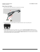
Step 3: Assemble the Cable
You will be attaching an outdoor-rated 24 AWG CAT5 cable (diameter .114 to .250 inches/2.9 to 6.4 mm) (not provided)
to the Power-over-Ethernet port on the back of the unit and weatherproofing the assembly later in the installation
procedure. First, you must construct the cable and assemble the weatherproofing cable covers as described in the
following steps. Proxim greatly simplifies this assembly process by offering pre-assembled CAT5 cable kits in 25m, 50m,
and 75m lengths (part numbers 69819, 69820, and 69821, respectively).
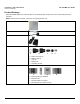
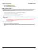
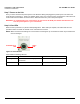
1. Slide the sealing nut (A) over the bare end of the CAT5 cable.
2. Slide the lock nut (B) over the bare end of the CAT5 cable.
3. Slide the sealing cap (C) over the bare end of the CAT5 cable. Make sure the red rubber gasket is inside the cap.
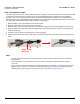
4. Apply two wraps of 0.5” wide Teflon tape (not supplied with unit) around the threads of the lock nut (B) that will go
inside the sealing cap.
5. Thread the lock nut (B) onto the sealing cap (C), and hand tighten.
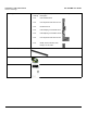
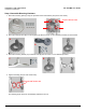
6. Terminate the RJ45 connectors (D) to both ends of the CAT5 cable; test for proper wiring (using a straight-through
cable).
NOTE:
• The cable must feed through all parts of the weatherproof cap before the RJ45 is crimped on the outdoor
Ethernet cable.
• The cable between the power injector and the unit must be a straight-through Ethernet cable (without
crossover).
• Due to variance in CAT5 cable diameter, termination techniques of the installer, and the application of proper
tightness of the connectors, it is strongly recommended that all cable connectors are secured by external
weatherproofing. This process will be described in Step 10: Weatherproof the Connectors.
BAC
Apply Teflon
tape here
D