Quick Install Guide ORiNOCO AP-4000MR-LR ORiNOCO AP-4900MR-LR Part Number 73305/2 (Print version) Part Number 73307/2 (CD version)
Notices © 2007 Proxim Wireless Corporation. All rights reserved. Covered by one or more of the following U.S. patents: 5,231,634; 5,875,179; 6,006,090; 5,809,060; 6,075,812; 5,077,753. This User Guide and the software described in it are copyrighted with all rights reserved. No part of this publication may be reproduced, transmitted, transcribed, stored in a retrieval system, or translated into any language in any form by any means without the written permission of Proxim Wireless Corporation.
Introduction The AP-4000MR-LR and AP-4900MR-LR are ruggedized tri-mode APs optimized for outdoor deployments. They are equipped with the following embedded radios: ▪▪ AP-4000MR-LR: One embedded 5.8 GHz (802.11a) radio and one embedded 2.4 GHz (802.11b/g) radio, enabling simultaneous support of 802.11a, 802.11b, and 802.11g clients. The unit also supports Mesh operation on either the 2.4 or 5.8 GHz band. ▪▪ AP-4900MR-LR: One embedded 4.9 GHz radio and one embedded 2.4 GHz (802.
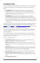
Note: This product does not contain internal antennas. At least one external antenna must be used to make the product operational. For information on antennas authorized for use with this product, refer to the Safety and Regulatory Compliance Guide on the installation CD.
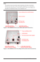
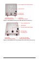
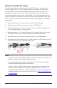
Figure 3: AP-4900MR-LR Unit (Dual LEDs and Serial Connection) Figure 4: AP-4900MR-LR FC Unit (Single LED and No Serial Connection) All rights reserved Page 5
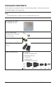
Package Contents Each shipment includes the items in the following table. Verify that you have received all parts of the shipment. Note: Unless listed here, cables are not included with the unit. AP-4000MR-LR Unit or AP-4900MR-LR Unit RJ11 to DB9 serial connector (not included with FC units) Installation CD (1 ea.) Power Injector and Cord (1 ea.) Cable Termination Kit Kit includes: A. RJ45 connectors (2) B. Sealing caps (2) C. Lock nut D. Sealing nut E.
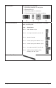
Mounting Kit Kit includes the following: A. Mounting bracket for wall/pole B. Extension arm C. Mounting plate to enclosure D. Mounting bracket for pole mounting A Mounting Hardware B C D The following mounting hardware is included with mounting kit: Qty. Description 6 ea Plain washer #5/16 2 ea. Hex cap screw NC 5/16-18 x 35 2 ea. Nut NC 5/16-18 4 ea. Helical spring lock washer # 1/4 4 ea. Helical spring lock washer #5/16 2 ea Hex cap screw NC 5/16-18 x 80 4 ea.
Hardware and Software Installation IMPORTANT! Before installing this product, see Safety and Regulatory Compliance Information on the product CD for important information. IMPORTANT! All units must be installed by a suitably trained professional installation technician or by a qualified installation service. Warning! To ensure proper grounding, use the hole at the bottom point on the back of each unit and the provided grounding screws to attach a ground wire of at least 10 AWG stranded to each unit.
Step 1: Choose a Location To make optimal use of the unit, you must find a suitable location for the hardware. The range of the radio unit largely depends upon the position of the antenna. Proxim recommends you do a site survey, observing the following requirements, before mounting the hardware. ▪▪ The location must allow easy disconnection of power to the radio if necessary. ▪▪ Air must be able to flow freely around the hardware. ▪▪ The radio unit must be kept away from vibration and excessive heat.
Step 3: Assemble the Cable You will be attaching an outdoor-rated 24 AWG CAT5 cable (diameter .114 to .250 inches/2.9 to 6.4 mm) (not provided) to the Power-over-Ethernet port on the back of the unit and weatherproofing the assembly later in the installation procedure. First, you must construct the cable and assemble the weatherproofing cable covers as described in the following steps.
Step 4: Assemble Mounting Hardware 1. Attach the mounting plate (A) using the provided screws and washers (Torque 9 N∙m/75 in-lbs) 2. Attach the extension arm (B) to mounting piece (A) with the screw, nut, and washers. 3. Attach the mounting bracket (C) to extension arm (B) with the screw, nut, and washers provided. 4. Tighten assembly (Torque 15 N∙m/130 in-lbs). The following figure shows the full assembly attached to the unit.
Step 5: Mount the Unit IMPORTANT! If the AP is going to be used as part of a Mesh network, you will need to perform initial configuration of the parameters mentioned in the Prerequisites section of this AP-4000MR-LR/AP-4900MR-LR User Guide before you mount the unit. See the User Guide for more information on configuring these parameters. Caution: To ensure that water does not gather around the antenna connectors, mount the unit with the antenna connectors facing downward. 1.
Step 6: Plug in the Cables 1. Plug one end of the CAT5 cable (A) into the RJ45 jack of the unit (B). Note: On FC versions, connect the cable to the port labeled “J1 Antenna” on the power injector (not pictured). This port has 48 VDC power on the RJ45. 2. Connect the free end of the CAT5 cable to the “Data and Power Out” port on the power injector. 3.
If you are connecting the PC directly to the unit, use a crossover Ethernet cable between the network interface card in the PC and the RJ45 “Data In” port on the power injector. Note: On FC units, connect the cross-over cable between the network interface card in the PC and the and the RJ45 “J2 PC/Router” port on the power injector (not pictured).
Step 7: Power on the Unit The power injector provides Power-over-Ethernet (PoE), supplying electricity and wired connectivity to the unit over a single 24 AWG CAT5 (diameter .114 to .250 inches/2.9 to 6.4 mm). The unit is not 802.3af-compatible. Always use the supplied power injector to ensure that the unit is powered properly. Note that the Active Ethernet module provides +48 VDC over a standard CAT5 Ethernet cable.
Step 8: View LEDs On most units, the LEDs are present at the unit’s Ethernet connector; unscrew the watertight cap if necessary to view the LEDs. NOTE: Make sure the domed sealing nut is loose before unscrewing the cap or the Ethernet cable may be twisted and damaged. When the unit is powered on, it performs startup diagnostics.
Step 9: Tighten the Cables 1. Apply two wraps of Teflon tape around the threads of the unit’s RJ45 jack (A) in a clockwise direction. 2. Make sure that the red rubber gasket is still seated in the sealing cap of the sealing cap/lock nut assembly (B). 3. Slide the sealing cap/lock nut assembly (B) over the RJ45 jack (A) and thread onto enclosure. Hand tighten first, then use a pipe wrench or similar tool to tighten one more quarter turn. Caution! Do not over-tighten! 4.
Step 10: Weatherproof the Connectors After you have fully assembled and tightened the cable, use the provided self-fusing, rubber-based tape strip and electrical tape (not provided; Proxim recommends Scotch™ Super 33+ Vinyl Electrical Tape) to seal the connection, as follows. 1. Remove the film liner from the rubber-based tape strip, and stretch the tape until it is approximately half of its original width.
Step 11: Install Documentation and Software To install the documentation and software on a computer or network: 1. Place the installation CD in a CD-ROM drive. The installer normally starts automatically. (If the installation program does not start automatically, click setup.exe on the installation CD.) 2. Follow the instructions displayed on the installer windows.
Unit Initialization Using ScanTool ScanTool is a software utility that is included on the installation CD-ROM. It is an initial configuration tool that allows you to find the IP address of an Access Point by referencing the MAC address in a Scan List, or to assign an IP address if one has not been assigned. The tool automatically detects the Access Points installed on your network, regardless of IP address, and lets you configure each unit’s IP settings.
Note: If your Access Point does not appear in the Scan List, click the Rescan button to update the display. If the unit still does not appear in the list, see the Troubleshooting chapter in the AP-4000MR-LR/4900MR-LR User Guide for suggestions. Note that after rebooting an Access Point, it may take up to five minutes for the unit to appear in the Scan List. 4. Do one of the following: ▪▪ ▪▪ If the AP has been assigned an IP address by a DHCP server on the network: a.
c. Set IP Address Type to Static. d. Enter a static IP Address for the AP in the field provided. You must assign the unit a unique address that is valid on your IP subnet. e. Enter your network’s Subnet Mask. f. Enter your network’s Gateway IP Address. g. Enter the SNMP read/write password in the Read/Write Password field. For new units, the default password is public h. Click OK to save your changes. i. The Access Point will need to reboot to apply any changes you made.
5. Enter the HTTP password in the Password field. Leave the User Name field blank. For new units, the default HTTP password is public. If you are logging on for the first time the Setup Wizard will launch automatically. Note Setup Wizard will not relaunch on subsequent logins. To force the Setup Wizard to launch upon login, click Management > Services and choose Enable from the Setup Wizard drop down menu. 6. To configure the AP using the Setup Wizard, see Using the Setup Wizard, below.
1. Click Setup Wizard to begin. The Setup Wizard supports the following navigation options: ▪▪ Save & Next Button: Each Setup Wizard screen has a Save & Next button. Click this button to submit any changes you made to the unit’s parameters and continue to the next page. The instructions below describe how to navigate the Setup Wizard using the Save & Next buttons. ▪▪ Navigation Panel: The Setup Wizard provides a navigation panel on the left-hand side of the screen.
Software Updates Proxim periodically releases updated software for the AP-4000MR-LR/4900MRLR on its support Web site, http://support.proxim.com. Proxim recommends that you check the Web site for the latest updates after you have installed and initialized the unit. Download the Software 1. In your web browser, go to http://support.proxim.com. 2. If prompted, create an account to gain access. Note: The Knowledgebase is available to all Web site visitors.
4. Use the Browse button to locate or manually type in the name of the file (including the file extension) you downloaded from the Proxim Knowledgebase. If typing the file name, you must include the full path and the file extension in the file name text box. 5. To initiate the HTTP Update operation, click the Update AP button. A warning message advises you that a reboot of the device will be required for changes to take effect. 7.
Frequencies and Bandwidths Available channels vary depending on product. 2.4 GHz Frequencies and Bandwidths (AP-4000MR-LR/4900MR-LR) Channel Center Frequency (MHz) 20 MHz 1 2412 2 2417 3 2422 4 2427 5 2432 6 2437 7 2442 8 2447 9 2452 10 2457 11 2462 12 2467 = Occupied bandwidth for specified center frequency.
4.9 GHz Frequencies and Bandwidths (AP-4900MR-LR only) Channel Center Frequency (MHz) 10 MHz 20 MHz 10 4945 NA 20 4950 30 4955 40 4960 40 4960 50 4965 60 4970 70 4975 80 4980 90 4985 NA = Occupied bandwidth for specified center frequency.
Identifying Your Hardware Variant You can verify which hardware version you are using through the HTTP Interface, as described below. Status Page On the Status page, locate the product ID and serial number at the top of the page. If the serial number contains “FC” (as shown in the following figure), you are using the FC hardware variant. Configure > System Page On the Configure > System page, locate the Descriptor field.
Monitor > Version Page On the Monitor > Version page, locate the Hardware Inventory row. If the serial number listed in that row contains “FC” or if the variant listed in that row is “3” (as shown in the following figure), you are using the FC hardware variant.
Technical services and support If you are having trouble utilizing your Proxim product, please review the AP4000MR-LR/4900MR-LR User Guide and the additional documentation provided with your product. If you require additional support, please refer to the “Technical Services and Support” chapter in the AP-4000MR-LR/4900MR-LR User Guide for details about the information you will need to gather before using the Support Options listed below.
www.proxim.