
Installation Guide

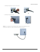
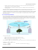
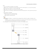
Table Of Contents
- Package Contents
- Getting Started
- Device Overview
- Device Installation
- Technical Specifications
- Device Models
- Accessories
- OFDM Modulation Rates
- Wireless Protocol
- Interfaces
- Transmit Power Specifications (5.150 to 5.850) GHz
- Transmit Power Specifications (2.400 to 2.484) GHz
- Receive Sensitivity (5.150 - 5.850) GHz
- Receive Sensitivity (2.400 to 2.484) GHz
- Power Supply
- Hardware Specifications
- Physical Specifications
- Environmental Specifications
- MTBF
- 6 Recommended Antennas
- Antenna Installation
- Measuring Signal Performance
- Lightning Protection
- Abbreviations
- Warranty and Technical Support
- Safety & Regulatory Information
Measuring Signal Performance
ORiNOCO
®
AP-9200R - Hardware Installation Guide 57
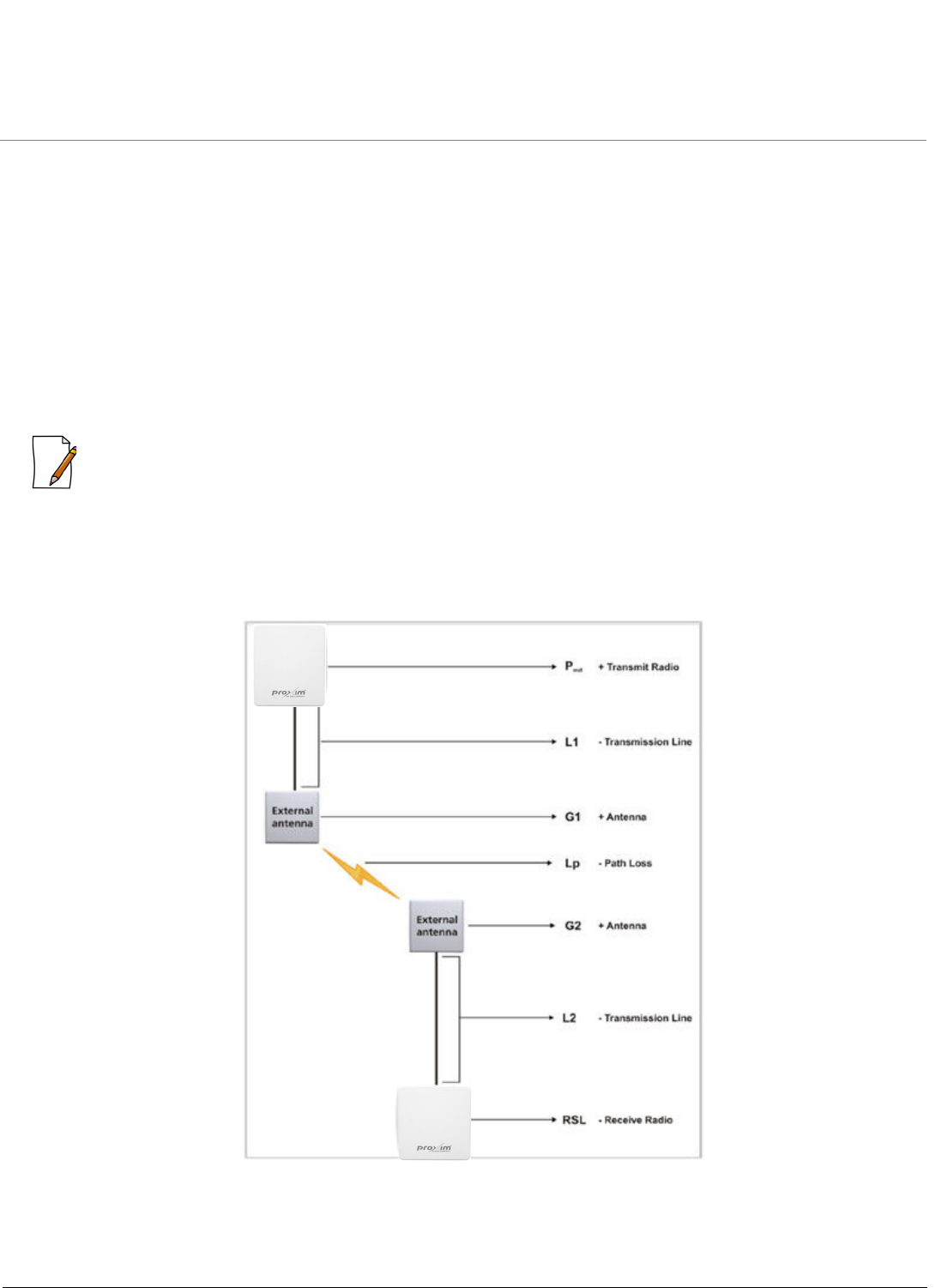
where:
• P
out
is the output power (in dBm) of the transmitter.
• L
1
is the total loss of all transmission elements between the antenna and the RF device on one side of the link (in dB).
• G
1
is the gain of the antenna on one side of the link (in dB).
• G
2
is the gain of the antenna on the opposite side of the link (in dB).
• L
2
is the total loss of all transmission elements between the antenna and the RF device on the opposite side of the link (in
dB).
• L
p
is the Path loss, defined by:
Lp (dB) = 96.6 + 20 log
10
F + 20 log
10
D; where:
– F is the frequency of the radio system in GHz.
– D is the distance of the path in miles.
:
• This formula is available on a calculation sheet provided by Proxim to generate an estimate of link distance and
reliability.
• The path loss must be smaller than the link budget minus the minimum required fade margin. The maximum ranges
cause the path loss plus the fade margin to be the same as the link budget.
The following figure is a pictorial representation of the elements in the Link Budget equation.
Figure 9-4 Link Budget Equation-Pictorial Representation