
Installation Guide
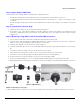
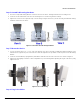
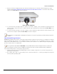
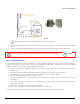
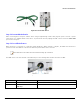
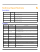
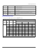
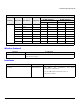
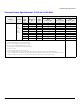
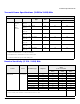
Table Of Contents
- Package Contents
- Getting Started
- Device Overview
- Device Installation
- Technical Specifications
- Device Models
- Accessories
- OFDM Modulation Rates
- Wireless Protocol
- Interfaces
- Transmit Power Specifications (5.150 to 5.850) GHz
- Transmit Power Specifications (2.400 to 2.484) GHz
- Receive Sensitivity (5.150 - 5.850) GHz
- Receive Sensitivity (2.400 to 2.484) GHz
- Power Supply
- Hardware Specifications
- Physical Specifications
- Environmental Specifications
- MTBF
- 6 Recommended Antennas
- Antenna Installation
- Measuring Signal Performance
- Lightning Protection
- Abbreviations
- Warranty and Technical Support
- Safety & Regulatory Information
Device Installation
ORiNOCO
®
AP-9200R - Hardware Installation Guide 15
.
Figure 4-6 Ground the Device
Step 12: Power ON the Device
After connecting the PoE Injector and the device using straight-through CAT5e cable plug the power cord into a power
outlet. There is no ON/OFF switch on the device. To power down the unit, unplug the RJ45 connector from the OUT / POE
port on the PoE injector.
Step 13: Port LED Indicators
When the device is powered on, it performs startup diagnostics. When startup is complete, the LEDs show the device’s
operational state. The LEDs are located on the Ethernet port inside the device enclosure.
: The LEDs will not be visible when the weather-sealing cap is installed.
The LEDs can be seen at the bottom of the Ethernet port. The following table describes the status of LEDs:
Figure 4-7 Port LED Indicators
LED State Off On
Status LED Ethernet link is down Ethernet link is active
Gigabit LED Ethernet link is established at
100 Mbps
Ethernet link is established at 1 Gbps