
Installation Guide
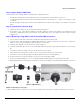
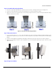
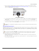
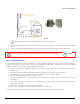
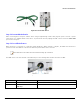
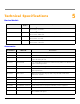
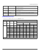
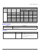
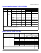
Table Of Contents
- Package Contents
- Getting Started
- Device Overview
- Device Installation
- Technical Specifications
- Device Models
- Accessories
- OFDM Modulation Rates
- Wireless Protocol
- Interfaces
- Transmit Power Specifications (5.150 to 5.850) GHz
- Transmit Power Specifications (2.400 to 2.484) GHz
- Receive Sensitivity (5.150 - 5.850) GHz
- Receive Sensitivity (2.400 to 2.484) GHz
- Power Supply
- Hardware Specifications
- Physical Specifications
- Environmental Specifications
- MTBF
- 6 Recommended Antennas
- Antenna Installation
- Measuring Signal Performance
- Lightning Protection
- Abbreviations
- Warranty and Technical Support
- Safety & Regulatory Information
Device Installation
ORiNOCO
®
AP-9200R - Hardware Installation Guide 12
Step 6: Assemble Mounting Hardware
1. Place the L-Shaped Mounting Bracket onto the bottom of the device and align with the four mounting holes.
2. Insert the screws and washers into the four mounting holes as shown in Figure 4-2 view (B).
3. Tighten the screws to the required torque. The last image in Figure 4-2 view (C) shows the fully assembled mounting
hardware attached to the device.
Figure 4-2 Assemble the Mounting Hardware
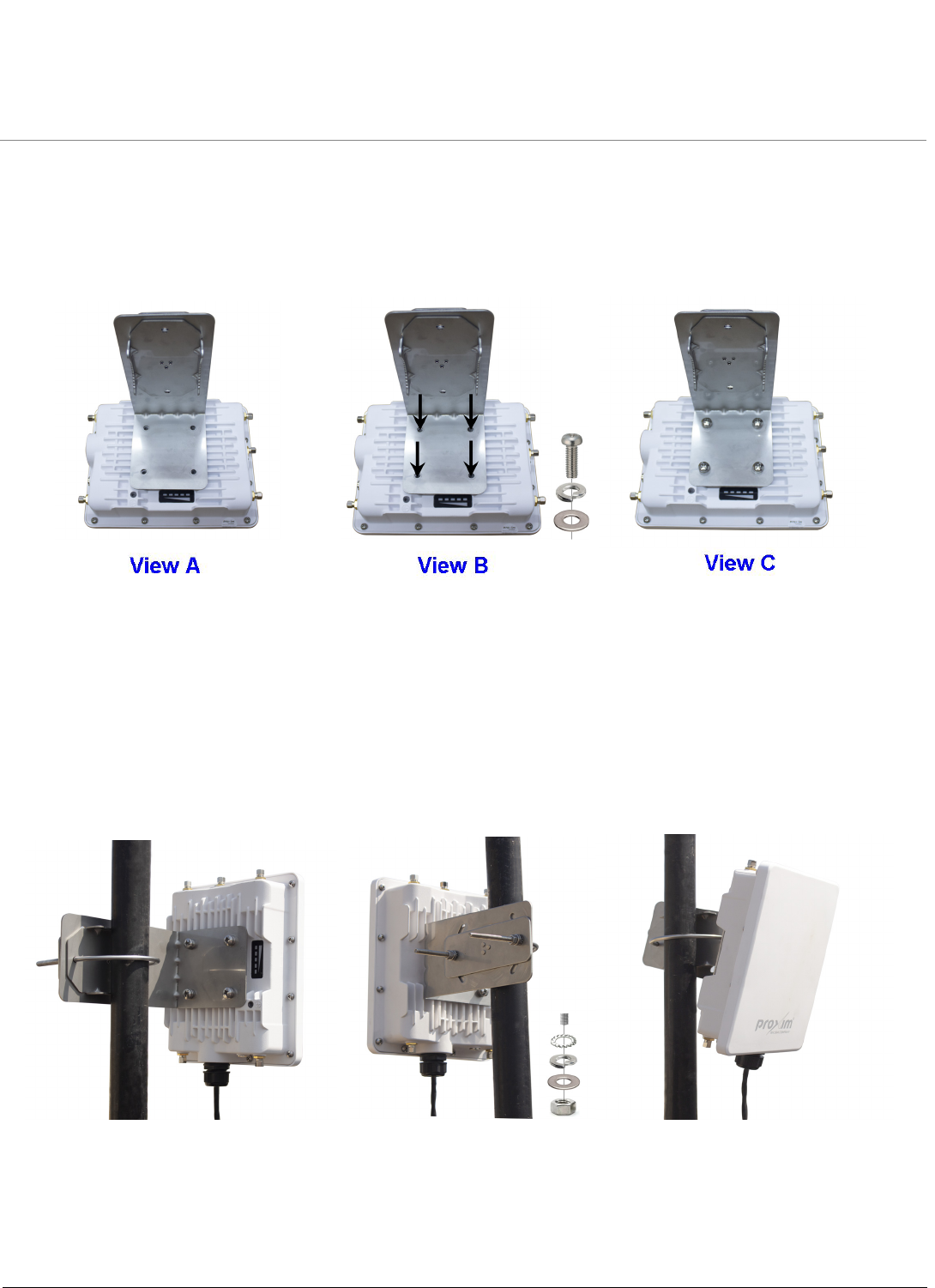
Step 7: Mount the Device
1. To pole-mount the device to a 1.5 to 3.25 inch diameter pole, place the fully assembled mounting hardware along
with the device against the pole and insert the U-bolt through the holes provided on full axis plate on the Mounting
Bracket.
2. Insert the Toothed Washer, Spring Washer, Flat Washer and Nut on both ends of the U-bolt as shown in Figure 4.
3. Tighten the nut slightly so that the U-bolt is adjustable for pole mounting. After adjusting the angle of the device, fully
tighten the nut.
Figure 4-3 Pole Mounting
Step 8: Plug in the Cables