
User's Manual Part 1


Installation and Initialization MeshMAX 5054 Series User Guide
22
Installation Procedure
Step 1: Choose a Location
To make optimal use of the unit, you must find a suitable location for the hardware. The range of the radio unit largely
depends upon the position of the antenna. Proxim recommends you do a site survey, observing the following
requirements, before mounting the hardware.
• The location must allow easy disconnection of power to the radio if necessary.
• Air must be able to flow freely around the hardware.
• The radio unit must be kept away from vibration and excessive heat.
• The installation must conform to local regulations at all times.
The unit is designed to directly mount to a pole or wall. Using the supplied mounting clamps and hardware, you can
mount the unit to a 1.25 inch to 4.5- inch pole (outside diameter). Using just one of the mounting clamps brackets, you
can mount it to a wall or other flat surface.
CAUTION: Proxim recommends the use of a lightning arrestor at the building ingress point. You can purchase the
Proxim Lightning Protector; see the documentation that comes with the Lightning Protector for more
information and installation instructions.
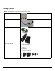
Step 2: Unpack the Shipping Box
1. Unpack the unit and accessories from the shipping box.
2. Note the Ethernet and wireless MAC addresses of the unit, as well as the serial number. The serial number is
required to obtain support from Proxim. Keep this information in a safe place.
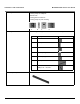
Step 3: Assemble the Cable
Use the Cable Termination Kit to assemble the cable. You will be attaching an outdoor-rated 24 AWG CAT5 cable
(diameter .114 to .250 inches/2.9 to 6.4 mm) (not provided) to the Power-over-Ethernet port on the back of the unit
and weatherproofing the assembly later in the installation procedure. First, you must construct the cable and
assemble the weatherproofing cable covers as described in the following steps. Proxim greatly simplifies this
assembly process by offering pre-assembled CAT5 cable kits in 25m, 50m, and 75m lengths (part numbers
69819, 69820, and 69821, respectively).
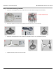
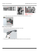
1. Slide the sealing nut (A) over the bare end of the CAT5 cable.
2. Slide the lock nut (B) over the bare end of the CAT5 cable.
3. Slide the sealing cap (C) over the bare end of the CAT5 cable. Make sure the red rubber gasket is inside the cap.
4. Apply two wraps of 0.5” wide Teflon tape (not supplied with unit) around the threads of the lock nut (B) that will go
inside the sealing cap.
5. Thread the lock nut (B) onto the sealing cap (C), and hand tighten.
6. Terminate the RJ45 connectors (D) to both ends of the CAT5 cable; test for proper wiring (using a straight-through
cable).
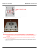
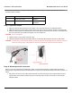
7. There are two DB9 connectors that connect to RJ11. The long one connects to Mesh and Access Point module
and the short one to the Subscriber module.
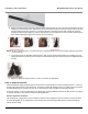
NOTE: The cable must feed through all parts of the weatherproof cap before the RJ45 is crimped on the outdoor
Ethernet cable. The cable between the power injector and the unit must be a straightthrough Ethernet cable
(without crossover). Due to variance in CAT5 cable diameter, termination techniques of the installer, and the
application of proper tightness of the connectors, it is strongly recommended that all cable connectors are
secured by external weatherproofing. This process will be described in Step 10: Weatherproof the Connectors.