
User's Manual


Page 16 Copyright © 2008 Proxim Wireless
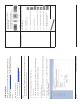
Step 8: View LEDs
The LEDs are present at the unit’s Ethernet connector; unscrew the watertight
cap if necessary to view the LEDs.
NOTE:
Make sure the domed sealing nut is loose before unscrewing the cap or the
Ethernet cable may be twisted and damaged.
When the unit is powered on, it performs startup diagnostics. When startup is
complete, the LEDs show the unit’s operational state, as follows:
LED State Power/Ethernet LED Radio LED
Blinking Green Power is on, unit is booting up,
Ethernet link is down.
Mesh radios are being initialized.
Steady Green Power is on, Ethernet link is up. Mesh radios are being
operational.
All rights reserved Page 17
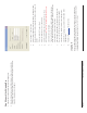
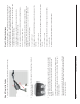
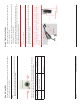
Step 9: Tighten the Cables
Apply two wraps of Tefl on tape around the threads of the unit’s RJ45 jack 1.
(A) in a clockwise direction.
Make sure that the red rubber gasket is still seated in the sealing cap of the 2.
sealing cap/lock nut assembly (B).
Slide the sealing cap/lock nut assembly (B) over the RJ45 jack (A) and 3.
thread onto enclosure. Hand tighten fi rst, then use a pipe wrench or similar
tool to tighten one more quarter turn.
Caution!
Do not over-tighten!
Tighten the lock nut (C) (Torque 4 N.m/35 in-lbs).4.
Thread the sealing nut (D) onto the sealing cap/lock nut assembly (B) and 5.
tighten (Torque 3 N.m/25 in-lbs).
Caution!
The lock nut (C) on the sealing cap/lock nut assembly (B) must
be fully tightened over the RJ45 connector before the sealing nut
(D) is fully tightened. Otherwise, the Ethernet cable may twist and
damage.