
User's Manual


Page 18 Copyright © 2008 Proxim Wireless
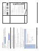
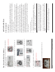
Step 10: Weatherproof the Connectors
After you have fully assembled and tightened the cable, use the provided
self-fusing, rubber-based tape strip and electrical tape (not provided; Proxim
recommends Scotch™ Super 33+ Vinyl Electrical Tape) to seal the connection,
as follows.
Remove the fi lm liner from the rubber-based tape strip, and stretch the 1.
tape until it is approximately half of its original width. This activates the
self-fusing action of the tape, which will set up over time to create a single,
waterproof mass.
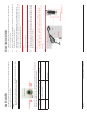
Stretch and wrap the tape around the connector tightly, starting below the 2.
connector cap and against the unit and wrapping in a clockwise direction.
Wrap the tape once around the base of the connector cap (A). Continue
to wrap the tape spirally around the connector in a clockwise direction,
maintaining a 50% width overlap (B). Continue wrapping the tape spirally
upward (C) until the tape extends onto the cable and you have used the
entire length of tape. Seal the tape tightly against the connector and the
cable (D).
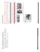
Note:
Be sure to wrap the tape in a clockwise direction; wrapping the tape in a
counterclockwise direction may loosen up the connector.
In the same manner as described in Step 2 above, apply a layer of black 3.
electrical tape (not provided) over the rubber-based tape for further
protection. Make sure the electrical tape also extends beyond the rubber-
based tape to seal it.
Repeat the weatherproofi ng procedure for other connectors as appropriate.4.
All rights reserved Page 15
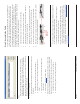
Step 7: Power on the Unit
The power injector provides Power-over-Ethernet (PoE), supplying electricity
and wired connectivity to the unit over a single 24 AWG CAT5 (diameter .114 to
.250 inches/2.9 to 6.4 mm). The unit is not 802.3af-compatible. Always use the
supplied power injector to ensure that the unit is powered properly. Note that
the Active Ethernet module provides +48 VDC over a standard CAT5 Ethernet
cable.
Once you have connected the power injector to the Ethernet cabling and
plugged the power injector cord into an AC outlet, the unit is powered on.
There is no ON/OFF switch on the unit. To remove power, unplug the AC cord
from the AC outlet or disconnect the RJ45 connector from the “Data and Power
Out” port on the power injector.
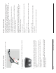
Press the Reload button (on the side of the power injector) for fi ve seconds
during power-up remotely resets the Mesh radios to their factory default
settings. You will need to use the end of a pin or paperclip to depress the
button.
WARNING!
To avoid damaging your router/switch, do not connect the RJ45
port labeled either “Data & Power Out” from the power injector to
your router/switch.
Press the Reload button (on the side of the power injector) to intiate the
Reload/Reset functionality. You may have to use the end of a pin or paperclip to
press the button.
If the Reload button is pressed for 5 to 10 seconds and then released, then
Mesh module moves to the bootloader state. If Reload button is pressed beyond
10 seconds, then the Mesh module’s Reload functionality is ignored.
If the Reload button is pressed for 10 to 20 sconds and released, then none of
the operation is performed and the Reload button is aborted.
If the Reload button is pressed for 20 seconds and above, then the Subscriber
module moves to reload state.
NOTE:
Bootloader will display all events to the serial console, which will guide user to
perform the Reload functionality.