
User's Manual


Page 22 Copyright © 2008 Proxim Wireless
Note:
If your unit does not appear in the Scan List, click the Rescan button
to update the display. If the unit still does not appear in the list, see the
Troubleshooting chapter in the MeshMAX 5054 User Guide for suggestions.
Note that after rebooting an Access Point, it may take up to fi ve minutes for
the unit to appear in the Scan List.
Do one of the following:4.
If the Mesh radio has been assigned an IP address by a DHCP server on ▪
the network:
Highlight the entry for the unit you want to confi gure.a.
Click the b. Change button. The Change screen appears (see
below).
Click on the c. Web Confi guration button at the bottom of the
change screen.
Proceed to the d.
Logging In section, below.
If the Mesh radio has not been assigned an IP address (in other words, ▪
the unit is using its default IP address, 169.254.128.132), follow these
steps to assign it a static IP address that is valid on your network:
Highlight the entry for the unit you want to confi gure.a.
Click the b. Change button. The Change screen appears.
All rights reserved Page 11
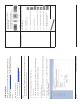
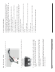
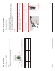
Step 3: Assemble the Cable
Use the Cable Termination Kit to assemble the cable. You will be attaching an
outdoor-rated 24 AWG CAT5 cable (diameter .114 to .250 inches/2.9 to 6.4
mm) (not provided) to the Power-over-Ethernet port on the back of the unit
and weatherproofi ng the assembly later in the installation procedure. First, you
must construct the cable and assemble the weatherproofi ng cable covers as
described in the following steps. Proxim greatly simplifi es this assembly process
by offering pre-assembled CAT5 cable kits in 25m, 50m, and 75m lengths (part
numbers 69819, 69820, and 69821, respectively).
Slide the sealing nut (A) over the bare end of the CAT5 cable.1.
Slide the lock nut (B) over the bare end of the CAT5 cable.2.
Slide the sealing cap (C) over the bare end of the CAT5 cable. Make sure 3.
the red rubber gasket is inside the cap.
Apply two wraps of 0.5” wide Tefl on tape (not supplied with unit) around 4.
the threads of the lock nut (B) that will go inside the sealing cap.
Thread the lock nut (B) onto the sealing cap (C), and hand tighten.5.
Terminate the RJ45 connectors (D) to both ends of the CAT5 cable; test for 6.
proper wiring (using a straight-through cable).
Notes:
The cable must feed through all parts of the weatherproof cap before the ▪
RJ45 is crimped on the outdoor Ethernet cable.
The cable between the power injector and the unit must be a straight- ▪
through Ethernet cable (without crossover).
Due to variance in CAT5 cable diameter, termination techniques of the ▪
installer, and the application of proper tightness of the connectors, it is
strongly recommended that all cable connectors are secured by external
weatherproofi ng. This process will be described in
Step 10: Weatherproof
the Connectors
.