
User's Manual


Tsunami MP.11 2454-R, 5054-R, and 5054-R-LR Installation and Management
Chapter 4. Basic Management 35
GENERAL CONFIGURATION SETTINGS
System Status
The status tab showing the system status is displayed automatically when you log into the Web interface. It is
also the default window displayed when you click the Status button on the left side of the window. See “View
System Status”
on page 40 for more information.
System Configuration
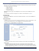
The System Configuration window lets you change the unit’s country, system name, location name, and so on
(see the window to the right). The Country selection is required to enable the correct parameters. The other
details help distinguish this unit from other routers, and let you know whom to contact in case of problems.
See “1) Configure System Parameters”
on page 42 for more information.
IP Configuration
The IP Configuration window lets you change the unit’s IP parameters. These settings differ between
Routing and Bridge mode. See “2) Configure Network Parameters”
on page 47 for more information.
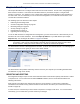
Interface Configuration
The Interface configuration pages let you change the Ethernet and Wireless parameters. The Wireless tab
is displayed by default when you click the Interfaces tab.
Ethernet
To configure the Ethernet interface, click the Configure button, the Interfaces tab, and the Ethernet
sub-tab. You can set the Configuration parameter from this tab for the type of Ethernet transmission.
The recommended setting is auto-speed auto-duplex. See “Configure the Ethernet Interface”
on page
67 for more information.
Wireless
To configure the wireless interface, click the Configure button followed by the Interfaces tab; then click
the Wireless sub-tab. For BSUs, the wireless interface can be placed in either WORP Base or WORP
Satellite mode (selected from the Interface Type drop-down box). SUs can be placed only in WORP
Satellite mode. (See “3) Configure Interface Settings”
on page 57 for more information.)
VLAN Configuration
To configure BSU VLAN parameters, click the Configure button followed by the VLAN tab; the BSU Table
tab is displayed. Click the SUs’ Table tab to configure SU VLAN parameters. Virtual LAN (VLAN)
implementation in the Tsunami MP.11 products lets the BSU and SU be used in a VLAN-aware network and
processes IEEE 802.1Q VLAN-tagged packets. Network resources behind the BSU and SU can be assigned
to logical groups. See “10) Configure VLAN Parameters”
on page 88 for more information.