
User's Manual


Tsunami MP.11 2454-R, 5054-R, and 5054-R-LR Installation and Management
Chapter 3. Management Overview 30
8. PPPoE Control
a. Ethertype (type 1, 0x8863)
9. PPPoE Data
a. Ethertype (type 1, 0x8864)
10. IP
a. Ethertype (type 1, 0x800)
11. ARP
a. Ethertype (type 1, 0x806)
12. Expedited Forwarding
a. IP TOS/DSCP (low=0x2D, high=0x2D, mask = 0x3F)
13. Streaming Video (IP/TV)
a. IP TOS/DSCP (low=0x0D, high=0x0D, mask = 0x3F)
14. 802.1p BE
a. Ethernet Priority (low=0, high=0) (this is the equivalent of the User Priority value in the TCI (Tag
Control Information) field of a VLAN tag)
15. 802.1p Voice
a. Ethernet Priority (low=6, high=6) (this is the equivalent of the User Priority value in the TCI (Tag
Control Information) field of a VLAN tag)
16. 802.1p Video
a. Ethernet Priority (low=5, high=5) (this is the equivalent of the User Priority value in the TCI (Tag
Control Information) field of a VLAN tag)
17. L2 Broadcast/Multicast
a. Ethernet Destination (dest = 0x80000000, mask = 0x80000000)
Two different VoIP rule names have been defined for each direction of traffic, Uplink (UL) and Downlink (DL),
(index numbers 2 to 5). This has been done to distinguish the proprietary nature of the Cisco VoIP implementation
as opposed to the more standard Session Initiation Protocol (SIP) signaling found, for example, in the Vonage-
type VoIP service.
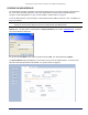
Service Flow Class (SFC)
A Service Flow class defines a set of parameters that determines how a stream of application data that matches a
certain classification profile will be handled. The software allows to create up to 32 different SFs, including seven
predefined SFs. The software provides the ability to create, edit, and delete SFs that contain the following
parameters and values:
• Service flow name
• Scheduling type – Best Effort (BE); Real-Time Polling Service (RtPS)
• Service Flow Direction – Downlink (DL: traffic from BSU to SU); Uplink (UL: traffic from SU to BSU)
• Maximum sustained data rate (or Maximum Information Rate, MIR) – specified in units of 1 Kbps from 8
Kbps up to the maximum rate of 108000 Kbps per SU
• Minimum reserved traffic rate (or Committed Information Rate, CIR) – specified in units of 1 Kbps from 0
Kbps up to the maximum rate of 10000 Kbps per SU
• Maximum Latency – specified in increments of 5 ms steps from a minimum of 5 ms up to a maximum of
100 ms
• Tolerable Jitter – specified in increments of 5 ms steps from a minimum of 0 ms up to the Maximum
Latency (in ms)
• Traffic priority – zero (0) to seven (7), 0 being the lowest, 7 being the highest
• Maximum number of data messages in a burst – one (1) to four (4), which affects the percentage of the
maximum throughput of the system according to the table
on page 62
• Activation state – Active; Inactive