
User's Manual


Tsunami MP.11 2454-R, 5054-R, and 5054-R-LR Installation and Management
Chapter 2. Installation 13
Notes:
• The cable must feed through all parts of the weatherproof cap before the RJ45 is crimped on the
outdoor Ethernet a cable.
• The cable between the power injector and the 5054-R or 2454-R must be a straight-through Ethernet
cable (without crossover).
• Due to variance in CAT5e cable diameter, termination techniques of the installer, and the application
of proper tightness of the connectors, it is strongly recommended that the CAT5e cable connector
and the serial connector cap are further secured by external weatherproofing (in addition to the
antenna N connector, where applicable). Butyl weatherproofing tape is the preferred material for
securing any external connector.
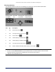
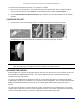
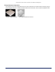
3. Screw mounting piece (A) to the back of the unit with 4 screws and washers (B) as shown (TORQUE 75 IN-LBS):
The arrow on the back of the unit indicates the direction to mount for vertical polarization when the unit has an
integrated antenna. These units should be mounted with the upper portion of the bracket in the position
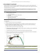
circled in the following figure on the left for vertical alignment when not using the bracket connector C.
For horizontal alignment, mount the integrated-antenna unit as shown in the figure on the right. Due to the 90˚
angle between the connecting surfaces on the bracket connector C, the orientation of vertical and horizontal
changes when adding the bracket.
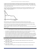
The following figure shows brackets mounted for vertical alignment:
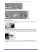
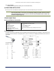
4. Attach bracket connector (C) to mounting piece (A) with the screw and nut provided, as shown below. This
extension piece gives the unit more possible tilt, letting you adjust for azimuth or elevation over a larger angle.