Part Number 72235r1 Tsunami MP.11 Models 2454-R, 5054-R, and 5054-R-LR Installation and Management Version 2.
Tsunami MP.11 2454-R, 5054-R, and 5054-R-LR Installation and Management COPYRIGHT ©2006 Proxim Wireless Corporation, San Jose, CA. All rights reserved. Covered by one or more of the following U.S. patents: 5,231,634; 5,875,179; 6,006,090; 5,809,060; 6,075,812; 5,077,753. This manual and the software described herein are copyrighted with all rights reserved.
Tsunami MP.11 2454-R, 5054-R, and 5054-R-LR Installation and Management Contents CHAPTER 1. OVERVIEW .........................................................................................................................................6 About This Book ...................................................................................................................................................6 Reference Manual .........................................................................................
Tsunami MP.11 2454-R, 5054-R, and 5054-R-LR Installation and Management 3) Configure Interface Settings....................................................................................................................57 4) Configure SNMP Parameters..................................................................................................................67 5) Configure RIP Parameters ....................................................................................................................
Tsunami MP.11 2454-R, 5054-R, and 5054-R-LR Installation and Management Verifying Proper Operation of the VLAN Feature ......................................................................................128 Troubleshooting Link Problems........................................................................................................................128 General Check........................................................................................................................................
Tsunami MP.11 2454-R, 5054-R, and 5054-R-LR Installation and Management Chapter 1. Overview The Tsunami MP.11 Model 5054-R (hereinafter referred to as the 5054-R) and the Model 2454-R (hereinafter referred to as the 2454-R) are flexible wireless outdoor routers that let you design solutions for point-to-point links and point-to-multipoint networks. The Tsunami MP.11 is a product family comprising several products (such as the 5054-R Base Station Unit and Subscriber Unit).
Tsunami MP.11 2454-R, 5054-R, and 5054-R-LR Installation and Management Reference Manual As a companion to the Installation and Management manual, the Tsunami MP.11 Reference Manual provides the following supplemental information: Command Line Interface Documents the text-based configuration utility’s keyboard commands and parameters. Event Log Error Messages Documents the error messages that you may see in your Event Log. Alarm Traps Documents the traps that can be set for alarm notification.
Tsunami MP.11 2454-R, 5054-R, and 5054-R-LR Installation and Management Point-to-Point Link With a BSU and an SU, it is easy to set up a wireless point-to-point link as depicted in the following figure.
Tsunami MP.11 2454-R, 5054-R, and 5054-R-LR Installation and Management POWER-OVER-ETHERNET The unit is equipped with an Active Ethernet module. Using Power-over-Ethernet (PoE), you can provide electricity and wired connectivity to the unit over a single Category 5 cable. Although the power injector that is supplied with the unit is 802.3af-compatible, standard 802.3af-compliant power modules will not properly power the units. Always use the supplied power injector.
Tsunami MP.11 2454-R, 5054-R, and 5054-R-LR Installation and Management Chapter 2. Installation This chapter describes the steps required to install and mount the unit, and to align the antenna. An antenna cable is required only when you use the external antenna option. Note that the unit must have either the integrated antenna or must be connected to an external antenna for its operation. The installation procedure does not include the mounting and connection of antennas. See the Tsunami MP.
Tsunami MP.11 2454-R, 5054-R, and 5054-R-LR Installation and Management Mounting Hardware The mounting hardware can be one of the following two mounting kits, plus the hardware listed below. Mounting Clamp for wall/pole Extension Arm Mounting Plate Mounting Clamp to enclosure for pole mounting Item Qty Description 1 6 ea. Plain washer #5/16 2 2 ea. Hex Cap Screw NC 5/16-18 x 35 3 2 ea. Nut NC 5/16-18 4 4 ea. Helical Spring Lock Washer #1/4 5 4 ea.
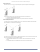
Tsunami MP.11 2454-R, 5054-R, and 5054-R-LR Installation and Management 2) PRE-ASSEMBLE THE HARDWARE Before mounting the unit, note the Ethernet and Mac addresses of the SU, as well as the serial number; these addresses may be used when configuring the BSU. The serial number is required to obtain support from Proxim. Keep this information in a safe place. The units are designed to directly mount to a pole. Using the supplied brackets and hardware, you can mount them to a 1.25 inch to 4.
Tsunami MP.11 2454-R, 5054-R, and 5054-R-LR Installation and Management Notes: • • • The cable must feed through all parts of the weatherproof cap before the RJ45 is crimped on the outdoor Ethernet a cable. The cable between the power injector and the 5054-R or 2454-R must be a straight-through Ethernet cable (without crossover).
Tsunami MP.11 2454-R, 5054-R, and 5054-R-LR Installation and Management 5. Attach bracket connector (C) to bracket (E) with the screw and nut provided. (TORQUE 130 IN-LBS) 3) CONNECT THE CABLES 1. If you have not already done so, connect the normal RJ45 connector on an outdoor-rated Cat5 cable to the “Data & Power Out” port on the power injector. 2. Attach the other end of the Cat 5 cable with RJ45 connector to the Power and Ethernet port on the back of the unit (see the following figure).
Tsunami MP.11 2454-R, 5054-R, and 5054-R-LR Installation and Management Note: If you are connecting the PC directly to the unit, you must use a crossover Ethernet cable between the network interface card in the PC and the RJ45 “Data In” port on the power injector. 4) POWERING ON THE UNIT Once you have connected the power injector to the Ethernet cabling and plugged the power injector cord into an AC outlet, the unit is powered on. There is no ON/OFF switch on the unit.
Tsunami MP.11 2454-R, 5054-R, and 5054-R-LR Installation and Management GREEN Power is on and the Ethernet link is up. RF (Wireless) Link RED Power is on, unit is self-heating BLINKING GREEN A wireless link is being established. GREEN A wireless link has been established. Note: The two LEDs also are continually blinking if there is any serious initialization error or when Ethernet and wireless connections both are not active.
Tsunami MP.11 2454-R, 5054-R, and 5054-R-LR Installation and Management To install the documentation and software on a computer or network: 1. Place the CD in a CD-ROM drive. The installer normally starts automatically. (If the installation program does not start automatically, click setup.exe at the following location to begin: \Docs\setup.exe .) 2. Click the Install Software and Documentation button and follow the instructions displayed on the installer windows. 7) MOUNTING THE UNIT 1.
Tsunami MP.11 2454-R, 5054-R, and 5054-R-LR Installation and Management To allow for precise antenna alignment, small changes in SNR result in large changes in the beep period. The alignment process averages the SNR, which is represented by an average length beep. When a higher SNR is received, the beep period is made shorter, dependent upon the difference to the average. A lower SNR results in a longer period between beeps.
Tsunami MP.11 2454-R, 5054-R, and 5054-R-LR Installation and Management set aad disable Disables Antenna Alignment Display (Ctrl-C also disables AAD). 9) COMPLETING INSTALLATION Be sure you have re-installed the waterproof caps on the serial and Ethernet port connections. Caution! Do not over-tighten the rear nut on the waterproof connector assembly. Over-tightening can cause the Cat 5 cable to crush and can subsequently damage the power injector or the unit.
Tsunami MP.11 2454-R, 5054-R, and 5054-R-LR Installation and Management External Antenna Connection One model of the SU has an integrated antenna; all other models have an external antenna connector (N-type) and no integrated antenna. For more information about external antennas, see the Antenna Installation Guide. SU with Integrated Antenna Chapter 2.
Tsunami MP.11 2454-R, 5054-R, and 5054-R-LR Installation and Management Chapter 3. Management Overview This chapter describes how to gain access to the unit for configuration and management. Connecting to the unit requires either: • A direct physical connection with an Ethernet cross-over cable or with a serial RS232C cable • A network connection For the serial connection, only the CLI can be used to configure and manage the unit.
Tsunami MP.11 2454-R, 5054-R, and 5054-R-LR Installation and Management The enterprise MIB (orinoco.mib) defines the read and read/write objects you can view or configure using SNMP. These objects correspond to most of the settings and statistics that are available with the other management interfaces. See the enterprise MIB for more information; the MIB can be opened with any text editor, such as Microsoft Word, Notepad, and WordPad. See “Configure SNMP Parameters” on page 67 for setup procedures.
Tsunami MP.11 2454-R, 5054-R, and 5054-R-LR Installation and Management 2. Select the unit for which you want to set the IP address and click Change. The Change dialog window is displayed, as shown in the following window. 3. To set the IP address manually, ensure that Static is selected as the IP Address Type and fill in the IP Address and Subnet Mask suitable for the LAN subnet to which the unit is connected. To set the IP address dynamically, ensure that Dynamic is selected as the IP Address Type.
Tsunami MP.11 2454-R, 5054-R, and 5054-R-LR Installation and Management STARTING THE WEB INTERFACE The Web Interface provides a graphical user interface through which you can easily configure and manage the unit. This section describes only how to access the Web Interface; the Web Interface itself described in “Chapter 4. Basic Management” on page 33 and “Chapter 5. Web Interface” on page 39. To use the Web Interface, you need only the HTTP password and IP address of the unit.
Tsunami MP.11 2454-R, 5054-R, and 5054-R-LR Installation and Management CHANGING BASIC CONFIGURATION INFORMATION To view or change basic system information, click the Configure button on the left side of the Web interface window, then click the System tab. See “Configure System Parameters” on page 42 for detailed information about the fields and selections in this window. Note: System Name by default contains the actual model number. The following screenshot is for information only.
Tsunami MP.11 2454-R, 5054-R, and 5054-R-LR Installation and Management Dynamic Frequency Selection (DFS) The Tsunami MP.11 5054-R supports Dynamic Frequency Selection (DFS) for European Telecommunications Standard Institute (ETSI) domains per EN 301-893 regulations. The ETSI requires that 802.11a devices use DFS to prevent interference with radar systems and other devices that already occupy the 5 GHz band.
Tsunami MP.11 2454-R, 5054-R, and 5054-R-LR Installation and Management Radar detection is performed only by the BSU and not by the SU. When an SU is set to a country in which DFS is used, it scans all available channels upon startup looking for a BSU that best matches its connection criteria (such as Base Station System Name, Network Name, and Shared Secret). The SU connects to the BSU automatically on whatever frequency the BSU has selected.
Tsunami MP.11 2454-R, 5054-R, and 5054-R-LR Installation and Management • Roaming will automatically select a channel on the SU corresponding to the BSU channel. Roaming is the procedure in which an SU terminates the session with the current BSU and starts the registration procedure with another BSU when it finds the quality of the other BSU to be better. VIRTUAL LOCAL AREA NETWORKS (VLANs) Virtual Local Area Networks (VLANs) are logical groupings of network hosts.
Tsunami MP.11 2454-R, 5054-R, and 5054-R-LR Installation and Management Concepts and Definitions The software supports QoS provisioning from the BSU only. You may define different classes of service on a BSU that can then be assigned to the SUs that are associated, or that may get associated, with that BSU.
Tsunami MP.11 2454-R, 5054-R, and 5054-R-LR Installation and Management 8. PPPoE Control a. Ethertype (type 1, 0x8863) 9. PPPoE Data a. Ethertype (type 1, 0x8864) 10. IP a. Ethertype (type 1, 0x800) 11. ARP a. Ethertype (type 1, 0x806) 12. Expedited Forwarding a. IP TOS/DSCP (low=0x2D, high=0x2D, mask = 0x3F) 13. Streaming Video (IP/TV) a. IP TOS/DSCP (low=0x0D, high=0x0D, mask = 0x3F) 14. 802.1p BE a.
Tsunami MP.11 2454-R, 5054-R, and 5054-R-LR Installation and Management Note that traffic priority refers to the prioritization of this specific Service Flow. The software tries to deliver the packets within the specified latency and jitter requirements, relative to the moment of receiving the packets in the unit. For delay-sensitive traffic the jitter must be equal to or less than the latency.
Tsunami MP.11 2454-R, 5054-R, and 5054-R-LR Installation and Management QoS Class A QoS class is defined by a set of parameters that includes the PIRs and SFCs that were previously configured. The software allows creating up to eight different QoS classes, including four predefined QoS classes. Up to four SF classes can be associated to each QoS class, and up to eight PIRs can be associated to each SF class.
Tsunami MP.11 2454-R, 5054-R, and 5054-R-LR Installation and Management Chapter 4. Basic Management This chapter describes how to configure and monitor the unit’s basic features. In most cases, configuring these basic features is sufficient. A full overview of the Web Interface is provided in “Chapter 5. Using the Web Interface” on page 40. The “Glossary” in the Tsunami MP.11 Reference Manual provides a brief explanation of the terms used.
Tsunami MP.11 2454-R, 5054-R, and 5054-R-LR Installation and Management Note: Saving of the unit’s configuration occurs only during a controlled reboot or by specifically issuing the CLI Save command. If you make changes to settings without a controlled reboot (command) and you have not issued the Save command, a power outage would wipe out all changes since the last reboot.
Tsunami MP.11 2454-R, 5054-R, and 5054-R-LR Installation and Management GENERAL CONFIGURATION SETTINGS System Status The status tab showing the system status is displayed automatically when you log into the Web interface. It is also the default window displayed when you click the Status button on the left side of the window. See “View System Status” on page 40 for more information.
Tsunami MP.11 2454-R, 5054-R, and 5054-R-LR Installation and Management MONITORING SETTINGS The unit offers various facilities to monitor its operation and interfaces. Only the most significant monitoring categories are mentioned here. Wireless To monitor the wireless interfaces, click the Monitor button and the Wireless tab. This tab lets you monitor the unit’s general performance and the performance of the WORP Base or WORP Satellite interfaces.
Tsunami MP.11 2454-R, 5054-R, and 5054-R-LR Installation and Management DEFAULT SETTINGS FEATURE / MODEL 5054-R 2454-R System Name Tsunami MP.11 5054-R Tsunami MP.11 2454-R Mode of Operation Bridge Bridge Routing Disabled Disabled IP Address Assignment Type Static Static IP Address 10.0.0.1 10.0.0.1 Subnet Mask 255.255.255.0 255.255.255.0 Default Router IP Address 10.0.0.1 10.0.0.
Tsunami MP.
Tsunami MP.11 2454-R, 5054-R, and 5054-R-LR Installation and Management UPGRADING THE UNIT The units are equipped with embedded software that can be updated when new versions are released. Updating the embedded software is described in “Download Files” on page 116, and in “Web Interface Image File Download” on page 120. A TFTP server is provided on the Documentation and Software CD; the server is required to transfer the downloaded file to the unit.
Tsunami MP.11 2454-R, 5054-R, and 5054-R-LR Installation and Management Chapter 5. Using the Web Interface This section covers the unit’s Web Interface. The interface is described hierarchically according to these buttons, which appear on the left side of the Web page: • • • • System Status below Configure on page 42 Monitor on page 108 Commands on page 116 Help and Exit buttons also appear; click the Help button to access online help; click the Exit button to exit the application.
Tsunami MP.11 2454-R, 5054-R, and 5054-R-LR Installation and Management View the Event Log Contents Click the Status button and the Event Log tab to view the contents of your event log. The event log keeps track of events that occur during the operation of the unit. The event log displays messages that may not be captured by System Traps, such as the Transmit Power for the Frequency Channel selected. See “Event Log Error Messages” in the Tsunami MP.
Tsunami MP.11 2454-R, 5054-R, and 5054-R-LR Installation and Management CONFIGURE THE UNIT’S SETTINGS Use the Configure section to change the unit’s settings. The following tabs are in this section: 1. 2. 3. 4. 5. 6. 7. 8. 9. 10. 11. 12.
Tsunami MP.11 2454-R, 5054-R, and 5054-R-LR Installation and Management Field Descriptions You can enter the following details: System Name This is the system name for easy identification of the BSU or SU. The System Name field is limited to a length of 32 bytes. Use the system name of a BSU to configure the Base Station System Name parameter on an SU if you want the SU to register only with this BSU.
Tsunami MP.11 2454-R, 5054-R, and 5054-R-LR Installation and Management Bridge and Routing Modes Bridge Mode A bridge is a product that connects a local area network (LAN) to another local area network that uses the same protocol (for example, Ethernet). You can envision a bridge as being a device that decides whether a message from you to someone else is going to the local area network in your building or to someone on the local area network in the building across the street.
Tsunami MP.11 2454-R, 5054-R, and 5054-R-LR Installation and Management Key Reasons to Use Routing Mode One key reason why customers would use Routing mode is to implement virtual private networks (VPNs) or to let nodes behind two different SUs communicate with each other. Many customers do this same thing in Bridging mode by using secondary interfaces on the router at the BSU or virtual interfaces at the BSU in VLAN mode to avoid some of the drawbacks of IP Routing mode.
Tsunami MP.11 2454-R, 5054-R, and 5054-R-LR Installation and Management Notes: • One of the most important details to pay attention to in Routing mode are the unit’s and the PC’s default gateways. It is a common mistake to set up the PC’s gateway to point to the SU when the SU is in Bridge mode and the BSU is in Routing mode. Always check to make sure the PCs on your network are configured to send their IP traffic to the correct default gateway.
Tsunami MP.11 2454-R, 5054-R, and 5054-R-LR Installation and Management 2) Configure Network Parameters Change IP Parameters The IP Configuration window lets you change the IP parameters. These settings differ when the unit is in Routing mode. Click the Configure button, the Network tab, and the IP Configuration sub-tab to view and configure local IP address information. See “Setting the IP Address” on page 22 for more information.
Tsunami MP.11 2454-R, 5054-R, and 5054-R-LR Installation and Management Configure Spanning Tree Options This protocol is executed between the bridges to detect and logically remove redundant paths from the network. Spanning Tree can be used to prevent link-layer loops (broadcast is forwarded to all ports where another device may forward it and, finally, it gets back to this unit; therefore, it is looping).
Tsunami MP.11 2454-R, 5054-R, and 5054-R-LR Installation and Management Configure IP Routes (Routing Mode only) Click the Configure button, the Network tab and the IP Routes sub-tab to configure IP routes. You cannot configure IP Routes in Bridge mode. In Routing mode, the Add Table Entries and Edit/Delete Table Entries buttons are enabled. Click the Add button to add entries; a window such as the following is displayed: Chapter 5.
Tsunami MP.11 2454-R, 5054-R, and 5054-R-LR Installation and Management Enter the route information and click Add. The IP Address and Subnet Mask combination is validated for a proper combination. Note: When adding a new entry, the IP address of the Route Destination must be in either the Ethernet subnet or in the wireless subnet of the unit. Click the Edit/Delete Table Entries button to make changes to or delete existing entries. Edit the route information and click OK.
Tsunami MP.11 2454-R, 5054-R, and 5054-R-LR Installation and Management • The normal scanning procedure starts when the average local SNR for the current BSU is less than or equal to the slow scanning threshold and the number of retransmitted frames is greater than the slow scanning threshold given in percentage. During the normal scanning procedure the SU scans the whole list of active channels while maintaining the current session uninterrupted.
Tsunami MP.11 2454-R, 5054-R, and 5054-R-LR Installation and Management Click the Configure button, the Network tab and the Roaming sub-tab to configure Roaming. The screen differs depending on whether the unit is configured as a BSU or as an SU. BSU Screen Enable or disable the Roaming feature by clicking on the Enable Roaming Status check box. The default value is disabled (clear). If you enable roaming, you may set the Announcement Period (from 25 to 100 ms, default is 100 ms).
Tsunami MP.11 2454-R, 5054-R, and 5054-R-LR Installation and Management Click Edit Table Entries to make changes; enter your changes and click OK. Note that an SU may roam from one BSU with a bandwidth setting to another BSU with a different bandwidth setting. Since in this case more channels need to be scanned than with only one channel bandwidth setting, it is important that the channel priority list mentioned above is properly used to limit scanning time.
Tsunami MP.11 2454-R, 5054-R, and 5054-R-LR Installation and Management SU Screen Enable or disable the Roaming feature in the Roaming Status drop-down box. The default value is disabled. Note: To enable roaming, you must enable Roaming Status on both the BSU and the SU. Enable and Configure the DHCP Server Click the Configure button, the Network tab and the DHCP Server sub-tab to enable the unit on a DHCP Server.
Tsunami MP.11 2454-R, 5054-R, and 5054-R-LR Installation and Management Field Descriptions DHCP Server Status Verify that DHCP Relay Agent is disabled. After you have made at least one entry in the DHCP server IP Pool Table, enable DHCP Server by selecting “Enable” from the DHCP Server Status pull-down menu. Note: There must be at least one entry in the DHCP server IP Pool Table to enable DHCP server. Also, DHCP server cannot be enabled if DHCP Relay Agent is enabled.
Tsunami MP.11 2454-R, 5054-R, and 5054-R-LR Installation and Management End IP Address Indicates the ending IP address that is used for assigning address to hosts on the Ethernet side in the configured subnet. Default Lease Time Specifies the default lease time for IP addresses in the address pool. The value is 3600-86400 seconds. Max Lease Time The maximum lease time for IP addresses in the address pool. The value is 3600-86400 seconds.
Tsunami MP.11 2454-R, 5054-R, and 5054-R-LR Installation and Management Enter the Server IP Address and any optional comments; click Add. Edit/Delete Entries to the DHCP Relay Agent Table Click Edit/Delete Table Entries to make changes; enter your changes and click OK. 3) Configure Interface Settings Configure the Wireless Interface To configure the wireless interface, click the Configure button followed by the Interfaces tab; then click the Wireless sub-tab.
Tsunami MP.11 2454-R, 5054-R, and 5054-R-LR Installation and Management Base Mode – US Country Field Descriptions Interface Type The interface type can be WORP Satellite or WORP Base. Network Name A Network Name is a name given to a network so that multiple networks can reuse the same frequency without problems. An SU can only register to its base if it has the same Network Name. The Network Name is one of the parameters that allow a Subscriber Unit to register on a Base Station.
Tsunami MP.11 2454-R, 5054-R, and 5054-R-LR Installation and Management SNR [dB] = signal level [dBm] – noise level [dBm] This information lets the sender adjust the transmission data rate to the optimal level to provide the best possible throughput. When you enable or disable WORP DDRS on the BSU, the BSU sends an announcement to the SUs and the SUs enable or disable WORP DDRS automatically.
Tsunami MP.11 2454-R, 5054-R, and 5054-R-LR Installation and Management Enable Turbo Mode Check this box to enable Turbo Mode. Turbo Mode is supported only in the United States, and only for the 5054-R. Turbo Mode uses three adjacent channels for wireless data transfer. Frequency Channel The frequency channel indicates the band center frequency the unit uses for communicating with peers. This frequency channel can be set in several ranges, depending upon regulatory domain. Refer to “Appendix A.
Tsunami MP.11 2454-R, 5054-R, and 5054-R-LR Installation and Management You can configure the Satellite Density to be Large, Medium, Small, Mini, or Micro. The default value for this setting is Large. The smaller settings are appropriate for high noise environments; a setting of Large would be for a low noise environment. A long distance link may have difficulty maintaining a connection with a small density setting because the wanted signal can disappear under the threshold.
Tsunami MP.11 2454-R, 5054-R, and 5054-R-LR Installation and Management active SFC is limited to send a single data message. Total throughput available to remaining best effort traffic is around 76% of the maximum available throughput.
Tsunami MP.11 2454-R, 5054-R, and 5054-R-LR Installation and Management Satellite Mode – US Country Field Descriptions All the fields that are common to both the BSU and the SU are applicable here. The SU features two additional fields: Base Station System Name (SU only) The name found on the system page of the BSU to which this SU is connecting.
Tsunami MP.11 2454-R, 5054-R, and 5054-R-LR Installation and Management Base Mode – Non-US Country Select a DFS preferred channel from the channels defined as “Disable” in the Channel Blacklist Table. Click Edit if you want to manually blacklist DFS channels. Field Descriptions The differences between the BSU Wireless interface screen for a non-US country and the equivalent screen for the US are: • • There is no Turbo Mode. Frequency Channel is not configurable.
Tsunami MP.11 2454-R, 5054-R, and 5054-R-LR Installation and Management channel blacklist list. It is not possible to select the DFS preferred channel from those channels in the DFS channel blacklist list indicated as “Enable”.
Tsunami MP.11 2454-R, 5054-R, and 5054-R-LR Installation and Management Satellite Mode – Non-US Country Field Descriptions The differences between the SU Wireless interface screen for a non-US country and the equivalent screen for the US are: • • There is no Turbo Mode. Frequency Channel is not configurable. Instead the channel is auto-selected by the DFS process. All the other fields that appear in the US screen for the SU are applicable.
Tsunami MP.11 2454-R, 5054-R, and 5054-R-LR Installation and Management Configure the Ethernet Interface To set the Ethernet speed, duplex mode, and input and output bandwidth limits, click the Configure button, the Interfaces tab, and the Ethernet sub-tab. You can set the desired speed and transmission mode by clicking on Configuration. Select from these settings for the type of Ethernet transmission: • Half-duplex means that only one side can transmit at a time.
Tsunami MP.11 2454-R, 5054-R, and 5054-R-LR Installation and Management Note the following: • There is no option to turn off receiving RIP advertisements. Once the unit is in Routing mode, it receives RIP updates when there is another RIP-enabled device advertising on your network. Although it receives and processes these updates, it does not further propagate these updates unless configured to advertise RIP. • The ability to enable or disable default route propagation is not user configurable.
Tsunami MP.11 2454-R, 5054-R, and 5054-R-LR Installation and Management RIP Example In the following example, assume that both the BSU and the SUs all are configured in Routing mode with RIP enabled to send and receive on both the Ethernet and Wireless interfaces. The network converges through updates until each unit has the following routing table: BSU 0.0.0.0 172.16.0.0 10.0.0.0 100.0.0.0 200.0.0.0 172.16.0.1 172.16.0.20 10.0.0.1 10.0.0.2 10.0.0.3 metric metric metric metric metric 1 1 1 2 2 10.0.0.
Tsunami MP.11 2454-R, 5054-R, and 5054-R-LR Installation and Management RIP Notes • Ensure that routers on the same physical network are configured to use the same version of RIP. • Routing updates occur every 30 seconds. It may take up to 3 minutes for a route that has gone down to timeout in a routing table. • RIP is limited to networks with 15 or fewer hops. 6) Configure Management Parameters When you click the Management button, the Passwords tab is displayed automatically.
Tsunami MP.11 2454-R, 5054-R, and 5054-R-LR Installation and Management HTTP (Web) Password The password for the Web browser HTTP interface. Enter a password in both the Password field and the Confirm field. The default password is public. Configure Service Parameters The Services tab lets you configure the SNMP, Telnet, and HTTP (Web Interface) parameters. Changes to these parameters require a reboot to take effect.
Tsunami MP.11 2454-R, 5054-R, and 5054-R-LR Installation and Management Telnet Configuration Settings Note: To use HyperTerminal for CLI access, make sure to check “Send line ends with line feeds” in the ASCII Setup window (click Properties from the HyperTerminal window; select Setup, then ASCII Setup. See “HyperTerminal Connection Properties” in the Tsunami MP.11 Reference Manual for more information).
Tsunami MP.11 2454-R, 5054-R, and 5054-R-LR Installation and Management 7) Configure Security Parameters Configure MAC Authentication Click the Configure button, the Security tab, and the MAC Auth sub-tab to build a list of authorized wireless stations that can register at the unit and access the network. MAC authentication is available only for Base Station units. This feature is supported on the wireless interface and only wireless MAC addresses should be entered in the list.
Tsunami MP.11 2454-R, 5054-R, and 5054-R-LR Installation and Management Configure RADIUS Authentication Click the Configure button, the Security tab, and the Radius Auth sub-tab to set the IP address of the RADIUS server containing the central list of MAC addresses that are allowed to access the network.
Tsunami MP.11 2454-R, 5054-R, and 5054-R-LR Installation and Management 8) Configure Packet Filtering Click the Configure button and the Filtering tab to configure packet filtering. Packet filtering can be used to control and optimize network performance. Filtering sub-tabs are as follows: The Filtering feature can selectively filter specific packets based upon their Ethernet protocol type. Protocol filtering is done at the Bridge layer.
Tsunami MP.11 2454-R, 5054-R, and 5054-R-LR Installation and Management Sample Use and Validation Configure the protocol filter to let only IP and ARP traffic pass through the MP.11 (bridge) from one network segment to another. Then, attempt to use Windows file sharing across the bridge. The file should not allow sharing; the packets are discarded by the bridge. Setting the ARP Filter There may be times when you need to set the ARP or Multicast.
Tsunami MP.11 2454-R, 5054-R, and 5054-R-LR Installation and Management Configure Ethernet Protocol Filtering The Ethernet Protocol Filter blocks or forwards packets based on the Ethernet protocols they support. Click the Configure button, the Filtering tab, and the Ethernet Protocol sub-tab to enable or disable certain protocols in the table. Entries can be selected from a drop-down box. Follow these steps to configure the Ethernet Protocol Filter: 1.
Tsunami MP.11 2454-R, 5054-R, and 5054-R-LR Installation and Management Add Entries to the Ethernet Protocol Filter Table To add an entry to the table, click Add Table Entries, select the protocol name from the drop-down box and click the Add button. To edit or delete table entries, click Edit/Delete Table Entries, make your changes or deletions, and click OK. Configure Static MAC Pair Filtering The Static MAC Address filter optimizes the performance of a wireless (and wired) network.
Tsunami MP.11 2454-R, 5054-R, and 5054-R-LR Installation and Management Click the Configure button, the Filtering tab, and the Static MAC sub-tab to access the Static MAC Address filter. Each MAC address or mask is comprised of 12 hexadecimal digits (0-9 and A-F) that correspond to a 48-bit identifier. (Each hexadecimal digit represents 4 bits (each bit represents the value 0 or 1).
Tsunami MP.11 2454-R, 5054-R, and 5054-R-LR Installation and Management Add Entries to the Static MAC Filter Table To add the entries to Filter table, click the Add Table Entries button. After entering the data, click the Add button. The entry is enabled automatically when saved. To edit an entry, click Edit. To disable or remove an entry, click Edit and change the Status field from Enable to Disable or Delete.
Tsunami MP.11 2454-R, 5054-R, and 5054-R-LR Installation and Management Static MAC Filter Examples Consider a network that contains a wired server and three wireless clients.