Introducing EZ Connect SERVICE MANUAL To learn more: visit www.proxess.
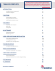
TABLE OF CONTENTS This Service Manual contains details for the Proxess CXSeries Lockset sold for 2021 (CX-B and CX-NB). For details about the CX-Series locksets sold prior to 2021 (CX-ST) please contact a Proxess representative or email info@proxess.com.
COPYRIGHT Copyright ©2018 Proxess, LLC. All rights reserved. Printed in the United States of America. Information in this document is subject to change without notice and does not represent a commitment on the part of Proxess, LLC. The software described in this document are furnished under a license agreement or nondisclosure agreement. This publication is intended to be an accurate description and set of instructions pertaining to its subject matter.
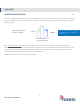
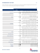
FUNCTIONS CONSTRUCTION FUNCTION 4-A All locks are supplied in Construction Function as a default and functions are meant to be reprogrammed at customer site prior to installation. There is one SKU (standard button) for all functions creating an inventory advantage over standard mechanical locks. Shading indicates that the lever is locked. Inside Outside All lock functions (Entrance, Storeroom, Lockdown, etc) are easily programmed electronically.
PROGRAMMABLE FUNCTIONS 5-B Unlike standard locks, Proxess has just one SKU allowing any lock to be supplied and programmed into numerous lock “functions” similar to standard locking functions shown in the chart below.
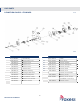
LOCK PARTS B FUNCTION CHASSIS – STANDARD 6-A 6-B ITEM 1 2 3 4 5 6 7 8 9 10 11 12 PART NUMBER C10-0040A A00-0001A C00-0001A C00-0006B C00-0016A C00-0012A C00-0011A C00-0041A C00-0018A C00-0021B C00-0036A C00-0020A CX-Series Service Manual DESCRIPTION Control Key Removeable Core Exterior Lever Exterior Trim Exterior Rose Chassis Plate Chassis Housing Through Hole Posts Exterior Backplate 6-Pin Ribbon Cable Exterior Trim Screws Exterior Gasket 6 ITEM 13 14 15 16 17 18 19 20 21 22 PART NUMBER C01-0031A
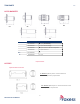
TRIM PARTS 7-C LATCH BACKSETS B5 ITEM B1 B2 B3* B4* B5* B6* B4 B3 B2 B1 B6 PART NUMBER C01-0030A C02-0030A C03-0030A C04-0030A C05-0030A C06-0030A DESCRIPTION 2 3/4" (Standard) 2 3/8” Round Edge 2 3/4” Drive-in & No Faceplate 2 3/8” Drive-in 5” 3 3/4” *Special Order LATCHES Optional latch extensions 5” Backset (70mm) latch + 57mm extension tube for 5" (127mm) requirement 3 ¾” Backset (60mm) latch + 35mm extension tube for 3¾" (95mm) requirement CX-Series Service Manual 7
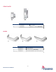
STRIKE PLATES S1 S2 ITEM S1 S2 PART NUMBER C01-0030A C02-0030A DESCRIPTION 2 ¾" strike ANSI 4 ⅞" strike (Standard) LEVERS 8 6 ITEM 6 8 9 CX-Series Service Manual PART NUMBER C06-0001A C08-0001A C09-0001A 9 DESCRIPTION Angled Return Curved Return (Standard) Curved No Return; (no lever return) 8
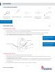
MAINTENANCE TOOLS FOR MAINTENANCE Lever Release Tool Philips Screwdriver, #2 9-A Core Turn Knob Tool (Included with lock) Cylinder and Core Testing Wrench Torx Wrench (Included with lock) Lockset can be quickly installed with only a Philips Screwdriver. REPLACING LEVERS 9-B TO REMOVE THE LEVER 1. If removing the exterior lever, first remove the removable core by inserting the control key and turning it 15 degrees clockwise. Then, pull out the removable core and key. 2.
DOOR PREPARATION AND INSTALLATION CYLINDRICAL INSTALLATION JIG KITS 10-A Light-duty, small quantities: Home improvement stores such as Home Depot and Lowes sell inexpensive kits from Ryobi, Milwaukee and DeWalt. Heavy-duty, industrial: Pro-Lock (“Killer Jig”) and Templaco (115-C3) offer kits.
TROUBLESHOOTING TROUBLESHOOTING HARDWARE The following table illustrates possible causes and solutions for common troubleshooting after installing the lock hardware. PROBLEM CAUSE Improper plug connection No beeps or blinks when the batteries are installed LED does not beep or blink on exterior when credential is presented MPD does not connect to the lock Red LED When credential is presented (Access Denied).
CX-SERIES INSTALLATION INSTRUCTIONS A. CHECKLIST (4 AA Batteries Included) FOR DOOR AND FRAME PREPARATION INSTRUCTIONS, SEE APPENDIX A OR GO TO PROXESS.COM Parts List: Each Proxess CX-Series lockset includes • Door Preparation Template • Cylindrical Lever Lockset with Installation Instructions • Exterior lock assembly (include housing, lever and cylinder drive unit) 1. 2. 3. 4. 5. 6. 7. 8. 9. 10. 11. 12.
B. ADJUST FOR DOOR THICKNESS Remove through bolt posts from chassis. Pull chassis and rose mounting plate from exterior lock assembly. PLEASE NOTE THAT THE LOCK BODY COMES PRE-SET TO ACCOMMODATE A 1¾ INCH DOOR Anti-Rotation Tabs on the rose mounting plate 1. Please follow the steps below: a. Rotate exterior rose mounting plate toward cylindrical chassis. b. Put the lever release tool into the allocated position of exterior rose mounting plate per the illustration below. c.
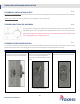
D. Hardware Installation Steps STEP 1 Install the latch in the door with the SP2 screws provided. The latch tube prongs should project into the chassis hole. STEP 4 (To Re-hand if Necessary) 1. To re-hand the lock chassis, begin by removing both the through bolt posts. See arrows below. 2. STEP 2 Install the strike plate with the SP3 screws provided, checking to make sure that the position of the deadlocking plunger is aligned against the strike plate. See Appendix A for Door Preparation Instructions.
STEP 6 STEP 8 Place the back plate on the interior of the door with the upper and lower screws near the chassis. Route the chassis cable through the square hole, and the exterior cable through the upper oval hole. Connect the chassis, exterior, and handle switch cables to the EZ connect board, leaving the exterior connection (6 pin rightmost connection) for the last connection. Ensure all cables are neatly tucked into the retaining clips on the rose plate.
STEP 10 Install the four AA batteries, beginning with the outer two. Insert first STEP 12 Install the levers onto the outside and inside of the door. See tips in CX-Series Service Manual for exterior handle installation and removal prior to installation. Insert last After the batteries are properly installed, the lock should beep once and the motor will run. The lock is then in the locked position. STEP 11 STEP 13 (If Necessary) Screw the battery cover onto the trim. Install the removable core.
APPENDIX A: INSTRUCTIONS FOR DOOR AND FRAME PREPARATION OF CYLINDRICAL LOCK A. CHECKLIST Tools for Door Preparation Drill Drill Bits: 1” (31/32” for drive in latch), 5/16” Hole Saw: 2-1/8” Phillips Screwdriver, #2 Hammer Chisel B. DOOR PREPARATION 1. Doors: Steel or Wood 2. Door thickness range: 1-3⁄8" (35mm) ~ 2" (51mm). 3. Match the Backset of your Proxess CX-Series lockset to the corresponding installation (either 2-3⁄8" [60 mm] or 2-3⁄4" [70 mm] Backset). 4.
ADDITIONAL RESOURCES SERVICE EQUIPMENT 18-A ENR™ Enrollment Reader and Programmer Proxess’ ENR™ makes the credential enrollment process intuitive and simple. Just place a credential on the desktop reader and a pop-up window automatically appears. From here you can create a new user, assign this card to an existing user, or view the details of an existing cardholder.
SOFTWARE SOLUTIONS FOR LOCKSET PROGRAMMING 19-B LoxIQ™ LoxIQ™ is a software app created by Proxess, LLC. Instead of requiring all the expensive components of an access system (approx. $3k/dr), LoxIQ™ requires only the locks, a phone, and a programmer. Although the system has the capability of unlimited doors and users, it is typically implemented in smaller systems of 100 doors/users or less…Expandable to full server system software. For more information about LoxIQ™, please visit our website: http://www.
FCC STATEMENT This equipment has been tested and found to comply with the limits for a Class B digital device, pursuant to Part 15 of the FCC Rules. These limits are designed to provide reasonable protection against harmful interference in a residential installation. This equipment generates, uses, and can radiate radio frequency energy and, if not installed and used in accordance with the instructions, may cause harmful interference to radio communication.