Introducing EZ Connect SERVICE MANUAL To learn more: visit www.proxess.
TABLE OF CONTENTS INTRODUCTION 3 DOCUMENTATION PACKAGE 3 CERTIFICATIONS AND STANDARDS 3 TECHNICAL SUPPORT 4 FUNCTIONS 4 LOCK FUNCTIONS LETTER CHART 4 LOCK PARTS 5 PARTS BLOWUP 5 PARTS NUMBER CHART 5 CASE AND STRIKE DIMENSIONS 6 CYLINDER/KEYING 6 TRIM PARTS 7 MAINTENANCE 7 TOOLS FOR MAINTENANCE 7 TROUBLESHOOTING HARDWARE 8 INSTALLATION MANUAL 9 MORTISE INSTALLATION DOOR PREP 10 MORTISE INTALLATION INSTRUCTIONS 12 MORTISE INSTALLATION TEMPLATE 21 ADDITIONAL RESOURCES 22
COPYRIGHT Copyright ©2018 Proxess, LLC. All rights reserved. Printed in the United States of America. Information in this document is subject to change without notice and does not represent a commitment on the part of Proxess, LLC. The software described in this document are furnished under a license agreement or nondisclosure agreement. This publication is intended to be an accurate description and set of instructions pertaining to its subject matter.
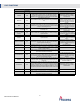
LOCK FUNCTIONS Mortise Lock Functions Name Entrance Similar ANSI # Mech Description Proxess Electronic Equivalent Function F109 Turn/Push button locking. Pushing and turning button on inside locks outside knob/lever requiring use of a key until button is manually unlocked. Push button locking. Pushing button locks the outside knob/lever until unlocked by key or by turning the inside lever/knob. Inside knob/lever always free.
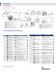
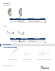
LOCK PARTS PARTS BLOWUP DEADBOLT (B) FUNCTIONS PART NUMBERS AND DESCRIPTIONS ITEM 1 2 3 4 5 6 7 8 9 10 11 12 13 14 15 16 17 18 19 PART NUMBER M00-0031A M00-0006A M00-0018A M00-0020A DESCRIPTION Cylinder Exterior Trim Exterior Backplate Gasket M00-0013A M00-0014A M00-0033A M00-0015A M00-0013A M00-0035A M00-0037A M00-0007A M00-0036A M00-0042A M00-0016A M00-0038A M00-0017A M00-0008A Spindle Spindle Spring Flat Head Screw (x2) Spring Cage Spindle Set Screw (Long) Counter Sink Screw (x4) Interior Trim Set
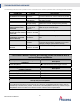
PROXESS MX CASE AND STRIKE DIMENSIONS CYLINDER/KEYING Due to the extra thick trim that houses RF and battery components, Proxess mortise locks will require special length (1 3 inch) cylinders. When using other manufacturers’ cylinders, ensure that you have the proper 1 3 inch long 4 4 cylinder. Proxess locks are supplied with only small format removable cores and we strongly recommend that these locks are keyed differently than other cylinders in the existing lock system.
TRIM PARTS STRIKE PLATES SB SL ITEM SL SB PART NUMBER M02-0030A M01-0030A DESCRIPTION Latch only strike plate Bolt and latch strike plate LEVERS 8 6 ITEM 6 8 PART NUMBER M06-0001A M08-0001A DESCRIPTION Angled Return Curved Return MAINTENANCE TOOLS FOR MAINTENANCE Philips Screwdriver, #2 Mortise Service Manual Core Turn Knob Tool 7 Cylinder and Core Testing Wrench
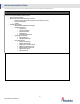
TROUBLESHOOTING HARDWARE The following table illustrates possible causes and solutions for common problems after installing the lock hardware.
INSTALLATION INSTRUCTIONS The following pages contain the Installation Manual for the MX- Series Mortise Lock A.
B. Door Preparation Measure the desired height from the floor to the door handle. Use the Mortise Lock Installation Template for prepping the Mortise door holes. Using the provided template, drill out the proper holes in the door. o Use a 3 4 inch hole saw to drill the hole for routing the cables through. If you do not have a hole saw, use a 1 2 inch drill bit and drill two holes. Lock Handing Note: The lock is right handed by default.
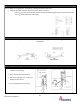
C.2 Remove Free Wheeling Lever Set Screw C.3 Proper Spring Cage Orientation Set Up (For Left Hand or Right-Hand Reverse) 1. For Exterior Panel Spring Cage- Place the spring cage on the exterior side of the trim. Arrow should point clockwise or in the direction you want the handle to engage the latch. 2. Then, screw in the two set screws. For Interior Panel Spring Cage – Arrow should point counterclockwise. See below. Note: arrow “B” must point down.
D.3 Proper Spring Cage Orientation Set Up (For Right Hand or Left Hand Reverse) The factory default setting will work with LHR and RH. The arrow should point in the direction you want the handle to engage with the latch. For Exterior Panel Spring Cage – Arrow should point counterclockwise. For Interior Panel Spring Cage – Arrow should point clockwise. Hardware Installation E. Mortise Chassis Installation . 1. Route the cables through the door hole. Use pliers if necessary. 2.
F.1 External Panel Installation 1. Ensure Ribbon Cable is secure in Exterior Trim first. Note that cable cannot be folded. 2. Then install Exterior Backplate and Gasket onto the Exterior Trim. F.2 Insert Spindle F.3 Insert Ribbon Cable 1. Insert the spindle (5) and spindle spring (6) into the spring cage. Ensure the lever rotates smoothly and drives the spindle properly. 1. Insert the ribbon cable into the oval opening on the side of the door. 2. Pull the ribbon cable through the other side of the door.
F.6 Install Cylinder F.7 Tighten Cylinder and Backplate 1. Insert the screwdriver into the side of the lock and tighten the cylinder. 2. Then, tighten the mortise lock set screw (22). 3. )Tighten interior backplate (17). 1. Loosen the cylinder set screw in the mortise chassis to insert the cylinder. 2. Insert the cylinder (1) into the front panel and ensure it sits flush with the front plate. Step F Completed G. Interior Assembly Preparation G.
G.2 Inserting Micro Switch CAM 1. Insert the Micro Switch Cam (18) on the spring cage as shown. Make sure the switch is engaged. 2. Then, move (18) to the right and align it with the spindle slot as shown. G.3 Inserting Spindles G.4 Engaging the Micro Switch Insert spindle (5) and spring (6) into the spring cage as shown. Turn the lever to make sure (18) is properly engaged with the Micro Switch. Note: The spring is not attached to anything and can be easily misplaced.
EZ Connect Wiring H. Interior Panel Installation H.1 Installing Thumb Turn Spindle and Connectors Insert Thumb Turn Spindle (15). H.2-3 Completed H.2 Then align the spindles with the chassis and place it onto the interior backplate. H.4 Turn the lever to ensure proper latch Ensure that the thumbturn is horizontal when the engagement. The latchbolt should retract. deadbolt is in, and vertical when the deadbolt is out/thrown. H.
I. Operation Test I.1 Insert AA Alkaline batteries (x4) into the battery compartment I.2 Green light will turn on and you will hear a beep, indication that the power is on I.3 Turn the lever and make sure the lever is free to rotate I.4 Testing the Lock 1. Take the credential, place it in front of the panel and wait for one second. The green light will flash and you should hear a beep. 2. Turn the handle to actuate the latch and the door can be opened.
J. Strike Plate Installation J.1 Use the template provided to create the strike plate mounting hole on the door frame. J.2 Insert the strike plate set screws (25) and (26). J.3 Repeat Section I.4 and Complete Installation.
INSTALLATION TEMPLATE – FOR REFERENCE ONLY: (USE THE TEMPLATE FROM MX INSTALLATION MANUAL FOR ACURATE DIMENSIONS) Mortise Service Manual 21
ADDITIONAL RESOURCES SERVICE EQUIPMENT ENR™ Enrollment Reader and Programmer Proxess’ ENR™ makes the credential enrollment process intuitive and simple. Just place a credential on the desktop reader and a pop-up window automatically appears. From here you can create a new user, assign this card to an existing user, or view the details of an existing cardholder.
SOFTWARE SOLUTIONS FOR LOCKSET PROGRAMMING LoxIQ™ LoxIQ™ is a software app created by Proxess, LLC. Instead of requiring all the expensive components of an access system (approx. $3k/dr), LoxIQ™ requires only the locks, a phone, and a programmer. Although the system has the capability of unlimited doors and users, it is typically implemented in smaller systems of 100 doors/users or less…Expandable to full server system software. For more information about LoxIQ™, please visit our website: http://www.
FCC STATEMENT This equipment has been tested and found to comply with the limits for a Class B digital device, pursuant to Part 15 of the FCC Rules. These limits are designed to provide reasonable protection against harmful interference in a residential installation. This equipment generates, uses, and can radiate radio frequency energy and, if not installed and used in accordance with the instructions, may cause harmful interference to radio communication.