SAS to SAS/SATA II RAID Subsystem User Manual Revision 1.
SAS to SAS/SATA II RAID Subsystem Table of Contents Preface ................................................................................................................................5 Before You Begin .............................................................................................................6 Safety Guidelines...............................................................................................................................................................
SAS to SAS/SATA II RAID Subsystem Chapter 4 RAID Configuration Utility Options .................................................... 37 4.1 Configuration through Terminal ....................................................................................................................37 4.2 Configuration through the LCD Panel.........................................................................................................43 4.2.1 4.3 Menu Diagram .............................................
SAS to SAS/SATA II RAID Subsystem 5.5.6 NTP Configuration.......................................................................................................................................89 5.5.7 View Events / Mute Beeper .....................................................................................................................90 5.5.8 Generate Test Event....................................................................................................................................
SAS to SAS/SATA II RAID Subsystem Preface About this manual This manual provides information regarding the hardware features, installation and configuration of the 16 Bays RAID subsystem. This document also describes how to use the storage management software. Information contained in the manual has been reviewed for accuracy, but not for product warranty because of the various environment/OS/settings. Information and specifications will be changed without further notice.
SAS to SAS/SATA II RAID Subsystem Before You Begin Before going through with this manual, you should read and focus on the following safety guidelines. Notes about the subsystem’s controller configuration and the product packaging and delivery are also included here.
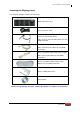
SAS to SAS/SATA II RAID Subsystem Unpacking the Shipping Carton The shipping package contains the following: RAID Subsystem Unit Two (2) power cords Two(2) external SAS cables Note: Four(4) external SAS cables for dual RAID controller One (1) RJ45 Ethernet cable Note: Two Ethernet cables for dual RAID controllers One (1) external serial cable RJ11-to-DB9 Note: Two serial cables for dual RAID controllers One(1) Controller Module Plate Cover NOTE: For Dual RAID Controller One(1) PSFM Plate Cover User Ma
SAS to SAS/SATA II RAID Subsystem Chapter 1 Product Introduction The EPICa RAID Subsystem The EP-3163 series RAID subsystem features 3Gb SAS host performance to increase system efficiency and performance. It features high capacity expansion, with 16 hotswappable SAS/SATA II hard disk drive bays in a 19-inch 3U rackmount unit, scaling to a maximum storage capacity in the terabyte range.
SAS to SAS/SATA II RAID Subsystem Features Supports dual controller for features redundant RAID Supports RAID levels 0, 1, 0+1, 3, 5, 6, 30, 50, 60 and JBOD Supports online Array roaming Online RAID level/stripe size migration Online capacity expansion and RAID level migration simultaneously Online Volume Set Expansion Supports multiple array enclosures per host connection Supports greater than 2TB per volume set Supports up to 128 LUNs Transparent data protection for
SAS to SAS/SATA II RAID Subsystem 1.
SAS to SAS/SATA II RAID Subsystem Bad block auto-remapping Yes Platform Rackmount Form Factor 3U # of Hot Swap Trays 16 Tray Lock Yes Disk Status Indicator Access / Fail LED Backplane SAS / SATA II Single BP # of PS/Fan Modules 500W x 2 w/PFC # of Fans 4 Power requirements AC 90V ~ 264V Full Range 10A-5A, 47Hz~63Hz Relative Humidity 10% ~ 85% Non-condensing Operating Temperature 10°C ~ 40°C (50°F ~ 104°F) Physical Dimension 590(L) x 482 (W) x 131(H) mm Weight (Without Disk) 18.
SAS to SAS/SATA II RAID Subsystem 1.2 RAID Concepts RAID Fundamentals The basic idea of RAID (Redundant Array of Independent Disks) is to combine multiple inexpensive disk drives into an array of disk drives to obtain performance, capacity and reliability that exceeds that of a single large drive. The array of drives appears to the host computer as a single logical drive.
SAS to SAS/SATA II RAID Subsystem Definition of RAID Levels RAID 0 is typically defined as a group of striped disk drives without parity or data redundancy. RAID 0 arrays can be configured with large stripes for multi-user environments or small stripes for single-user systems that access long sequential records. RAID 0 arrays deliver the best data storage efficiency and performance of any array type. The disadvantage is that if one drive in a RAID 0 array fails, the entire array fails.
SAS to SAS/SATA II RAID Subsystem RAID 3 sector-stripes data across groups of drives, but one drive in the group is dedicated for storing parity information. RAID 3 relies on the embedded ECC in each sector for error detection. In the case of drive failure, data recovery is accomplished by calculating the exclusive OR (XOR) of the information recorded on the remaining drives. Records typically span all drives, which optimizes the disk transfer rate.
SAS to SAS/SATA II RAID Subsystem RAID 6 is similar to RAID 5 in that data protection is achieved by writing parity information to the physical drives in the array. With RAID 6, however, two sets of parity data are used. These two sets are different, and each set occupies a capacity equivalent to that of one of the constituent drives. The main advantage of RAID 6 is High data availability – any two drives can fail without loss of critical data.
SAS to SAS/SATA II RAID Subsystem RAID Management The subsystem can implement several different levels of RAID technology. RAID levels supported by the subsystem are shown below. RAID Level Description Min. Drives 0 Block striping is provide, which yields higher performance than with individual drives. There is no redundancy. 1 1 Drives are paired and mirrored. All data is 100% duplicated on an equivalent drive. Fully redundant. 2 3 Data is striped across several physical drives.
SAS to SAS/SATA II RAID Subsystem 1.3 Array Definition 1.3.1 Raid Set A Raid Set is a group of disk drives containing one or more logical volumes called Volume Sets. It is not possible to have multiple Raid Sets on the same disk drives. A Volume Set must be created either on an existing Raid Set or on a group of available individual disk drives (disk drives that are not yet a part of a Raid Set). If there are existing Raid Sets with available raw capacity, new Volume Set can be created.
SAS to SAS/SATA II RAID Subsystem 1.4 High Availability 1.4.1 Creating Hot Spares A hot spare drive is an unused online available drive, which is ready to replace a failed disk drive. In a RAID level 1, 0+1, 3, 5, 6, 30, 50, or 60 Raid Set, any unused online available drive installed but not belonging to a Raid Set can be defined as a hot spare drive. Hot spares permit you to replace failed drives without powering down the system.
SAS to SAS/SATA II RAID Subsystem Chapter 2 Identifying Parts of the RAID Subsystem The illustrations below identify the various parts of the system. Familiarize yourself with the parts and terms as you may encounter them later in the later chapters and sections. 2.1 Main Components 2.1.
SAS to SAS/SATA II RAID Subsystem 2.1.1.1 Disk Trays HDD Status Indicator Part Function HDD Activity LED This LED will blink blue when the hard drive is being accessed. HDD Fault LED Green LED indicates power is on and hard drive status is good for this slot. If there is no hard drive, the LED is Red. If hard drive defected in this slot or the hard drive is failure, the LED is blinking red.
SAS to SAS/SATA II RAID Subsystem 2.1.1.2 LCD Front Panel Smart Function Front Panel The smart LCD panel is an option to configure the RAID subsystem. If you are configuring the subsystem using the LCD panel, press the Select button to login and configure the RAID subsystem. Parts Function Use the Up or Down arrow keys to go through the information on the LCD screen. This is also used to move between each menu when you configure the subsystem.
SAS to SAS/SATA II RAID Subsystem Environment Status LEDs Parts Function Power LED Green LED indicates power is ON. Power Fail LED If a redundant power supply unit fails, this LED will turn to RED and alarm will sound. Fan Fail LED When a fan fails or the fan’s rotational speed is below 1500RPM, this LED will turn red and an alarm will sound.
SAS to SAS/SATA II RAID Subsystem 2.1.1.3 LCD IP Address in Dual Controller Mode In dual controller mode, the RAID subsystem has 2 IP addresses which can be accessed separately. By default, the IP address of Controller 1 is shown. button in the To view the IP address of Controller 2, press the “Down Arrow” front panel three (3) times. When the IP address of Controller 1 is shown, there is no blinking rectangular character at the end of the IP address.
SAS to SAS/SATA II RAID Subsystem 2.1.
SAS to SAS/SATA II RAID Subsystem Controller Module – The subsystem has single or dual controller module. Power Supply / Fan Module #1, #2 – Two power supply / fan modules are located at the rear of the subsystem. Each PSFM has one Power Supply and two Fans. PSFM 1 has Power#1, Fan#1 and Fan#2. PSFM 2 has Power#2, Fan#3 and Fan#4. If the power supply fails to function, the Power Fail LED will turn red and an alarm will sound. An error message will also appear on the LCD screen warning of power failure.
SAS to SAS/SATA II RAID Subsystem 2.2 Controller Module The EPICa RAID system includes a dual 3Gb SAS-to-SAS/SATA II RAID Controller Module. RAID Controller Module 2.2.
SAS to SAS/SATA II RAID Subsystem Part Description Host Channel A, B Two host channels (A and B) are available and can be use to connect to SAS HBA on the Host system, or to connect to SAS switch. SAS Expansion Port Use for expansion; connect to the SAS In Port of a JBOD subsystem. Debug Port Use to check controller debug messages. Monitor Port Use to manage the RAID subsystem via serial terminal console. R-Link Port Use to manage the RAID subsystem via network and web browser.
SAS to SAS/SATA II RAID Subsystem 2.3 Power Supply / Fan Module (PSFM) The RAID subsystem contains two 500W Power Supply / Fan Modules. All the Power Supply / Fan Modules (PSFMs) are inserted into the rear of the chassis. 2.3.1 PSFM Panel The panel of the Power Supply/Fan Module contains: the Power On/Off Switch, the AC Inlet Plug, and a Power On/Fail Indicator showing the Power Status LED, indicating ready or fail. Each fan within a PSFM is powered independently of the power supply within the same PSFM.
SAS to SAS/SATA II RAID Subsystem NOTE: Each PSFM has one Power Supply and two Fans. PSFM 1 has Power#1, Fan#1 and Fan#2. PSFM 2 has Power#2, Fan#3 and Fan#4. When the Power Supply of a PSFM fails, the PSFM need not be removed from the slot if replacement is not yet available. The fan will still work and provide necessary airflow inside the enclosure. In replacing the failed PSFM, refer to section 6.3.2 of this manual.
SAS to SAS/SATA II RAID Subsystem Chapter 3 Getting Started with the Subsystem 3.1 Preparing the RAID Subsystem 1. Place the RAID subsystem in its proper place. 2. Connect the SAS cable(s) to the SAS Host Channel(s). 3. Attach network cable to the R-Link port. Connect the other end to your network hub or switch. Alternatively, you may use the Monitor port and connect the serial cable from the Monitor port to any available COM port of a PC. 3.2 Powering On 1.
SAS to SAS/SATA II RAID Subsystem 3.3 Disk Drive Installation This section describes the physical locations of the hard drives supported by the subsystem and give instructions on installing a hard drive. The subsystem supports hot-swapping allowing you to install or replace a hard drive while the subsystem is running. 3.3.1 Installing a SAS Disk Drive in a Disk Tray NOTE: These steps are the same when installing SATA disk drive in Single Controller Mode. 1.
SAS to SAS/SATA II RAID Subsystem 4. Place the hard drive in the disk tray. Turn the disk tray upside down. Align the four screw holes of the SAS disk drive in the four Hole A of the disk tray. To secure the disk drive into the disk tray, tighten four screws on these holes of the disk tray. Note in the picture below where the screws should be placed in the disk tray holes. Tray Hole A NOTE: All the disk tray holes are labelled accordingly.
SAS to SAS/SATA II RAID Subsystem 5. Slide the tray into a slot. 6. Press the lever in until you hear the latch click into place. The HDD Fault LED will turn green when the subsystem is powered on and HDD is good. 7. If necessary, lock the Disk Tray by turning the Lock Groove.
SAS to SAS/SATA II RAID Subsystem 3.3.2 Installing a SATA Disk Drive (Dual Controller Mode) in a Disk Tray 1. Remove an empty disk tray from the subsystem. 2. Prepare the dongle board and two screws. 3. Place the dongle board in the disk tray. Turn the tray upside down. Align the two screw hole of the dongle board in the two Hole D of the disk tray. Tighten two screws to secure the dongle board into the disk tray.
SAS to SAS/SATA II RAID Subsystem Tray Hole D NOTE: All the disk tray holes are labelled accordingly. 4. Place the SATA disk drive into the disk tray. Slide the disk drive towards the dongle board.
SAS to SAS/SATA II RAID Subsystem 5. Turn the disk tray upside down. Align the four screw holes of the SATA disk drive in the four Hole C of the disk tray. To secure the disk drive into the disk tray, tighten four screws on these holes of the disk tray. Note in the picture below where the screws should be placed in the disk tray holes. Tray Hole C NOTE: All the disk tray holes are labelled accordingly. 6. Insert the disk tray into the subsystem.
SAS to SAS/SATA II RAID Subsystem Chapter 4 RAID Configuration Utility Options Configuration Methods There are f o u r methods of configuring the RAID controller: a. VT100 terminal connected through the serial Monitor port b. Front panel touch-control buttons c. Web browser-based remote RAID management via the R-Link Ethernet port d. Telnet connection via the R-Link Ethernet port NOTE: The RAID subsystem allows you to access using only one method at a time.
SAS to SAS/SATA II RAID Subsystem 4. The default setting of the monitor port is 115200 baud rate, 8 data bit, non-parity, 1 stop bit and no flow control. 5. Click 38 disconnect button.
SAS to SAS/SATA II RAID Subsystem 6. Open the File menu, and then open Properties. 7. Open the Settings Tab. 8. Configure the settings as follows: “ Function, arrow and ctrl keys act as”: Terminal Keys “Backspace key sends”: Crtl + H “Emulation”: VT100 “Telnet terminal ID”: VT100 “Back scroll buffer lines”: 500 Click OK.
SAS to SAS/SATA II RAID Subsystem 9. Now, the VT100 is ready to use. After you have finished the VT100 Terminal setup, you may press t h e “X” key (in your Terminal) to link the RAID subsystem and Terminal together. Press “X” key to display the disk array Monitor Utility screen on your VT100 Terminal. 10. The Main Menu will appear.
SAS to SAS/SATA II RAID Subsystem Main Menu The main menu shows all function that enables the customer to execute actions by clicking on the appropriate link. NOTE: The password option allows user to set or clear the RA ID subsystem’s password protection feature. Once the password has been set, the user can only monitor and configure the RAID subsystem by providing the correct password. The password is used to protect the RAID subsystem from unauthorized access.
SAS to SAS/SATA II RAID Subsystem VT100 terminal configuration Utility Main Menu Options Select an option and the related information or submenu items display beneath it. The submenus for each item are shown in Section 4.2.1.
SAS to SAS/SATA II RAID Subsystem 4.2 Configuration through the LCD Panel All configurations can be performed through the LCD Display front panel function keys, except for the “Firmware update”. The LCD provides a system of screens with areas for information, status indication, or menus. The LCD screen displays menu items or other information up to two lines at a time. The RAID controller’s factory default password is set to 00000000.
SAS to SAS/SATA II RAID Subsystem 4.2.1 Menu Diagram The following menu diagram is a summary of the various configurations and setting functions that can be accessed through terminal. The LCD panel menus also have similar functions except Update Firmware.
SAS to SAS/SATA II RAID Subsystem User Manual 45
SAS to SAS/SATA II RAID Subsystem 46 User Manual
SAS to SAS/SATA II RAID Subsystem User Manual 47
SAS to SAS/SATA II RAID Subsystem 48 User Manual
SAS to SAS/SATA II RAID Subsystem User Manual 49
SAS to SAS/SATA II RAID Subsystem 4.3 Configuration through web browser-based proRAID Manager The RAID subsystem can be remotely configured via R-Link port with proRAID Manager, a web browser-based application. The proRAID Manager can be used to manage all available functions of the RAID controller. To configure the RAID subsystem from a remote machine, you need to know its IP Address. Launch your web browser from remote machine and enter in the address bar: http://[IP Address].
SAS to SAS/SATA II RAID Subsystem Main Menu The main menu shows all available function that user can execute by clicking on the appropriate hyperlink. Individual Category Description Quick Function Create a RAID configuration, which consists of all physical disks installed. The Volume Set Capacity, Raid Level, and Stripe Size can be modified during setup. Raid Set Functions Create customized Raid Sets.
SAS to SAS/SATA II RAID Subsystem Chapter 5 RAID Management 5.1 Quick Function 5.1.1 Quick Create The number of physical drives in the RAID subsystem determines the RAID levels that can be implemented with the Raid Set. This feature allows user to create a Raid Set associated with exactly one Volume Set. User can change the Raid Level, Capacity, Volume Initialization Mode and Stripe Size. A hot spare can also be created depending upon the existing configuration.
SAS to SAS/SATA II RAID Subsystem Tick on the Confirm The Operation o p t i o n and click on the Submit button in the Quick Create screen. The Raid Set and Volume Set will start to initialize. You can use RaidSet Hierarchy feature to view the Volume Set information (Refer to Section 5.6.1). NOTE: In Quick Create your Raid Set is automatically configured based on the number of disks in your system. Use the Raid Set Function and Volume Set Function if you prefer to customize the Raid Set and Volume Set.
SAS to SAS/SATA II RAID Subsystem 5.2 RAID Set Functions Use the Raid Set Function and Volume Set Function if you prefer to create customized Raid Sets and Volume Sets. User can manually configure and take full control of the Raid Set settings, but it will take a little longer to setup than the Quick Create configuration. Select the Raid Set Function to manually configure the Raid Set for the first time or t o delete existing Raid Set and reconfigure a R aid Set. 5.2.
SAS to SAS/SATA II RAID Subsystem 5.2.2 Delete RAID Set To delete a Raid Set, click on the Delete RAID Set link. A “Select The RAID SET To Delete” screen is displayed showing all Raid Sets existing in the system. Select the Raid Set you want to delete in the Select column. Tick on the Confirm The Operation and click on the Submit button to process with deletion. NOTE: You cannot delete a Raid Set containing a Raid 30/50/60 Volume Set. You must delete the Raid 30/50/60 Volume Set first.
SAS to SAS/SATA II RAID Subsystem 5.2.3 Expand RAID Set Use this option to expand a Raid Set, when one or more disk drives is/are added to the system. This function is active when at least one drive is available. To expand a Raid Set, click on the Expand RAID Set link. Select the Raid Set which you want to expand. Tick on the available disk(s) and check Confirm The Operation. Click on the Submit button to add the selected disk(s) to the Raid Set.
SAS to SAS/SATA II RAID Subsystem User Manual 57
SAS to SAS/SATA II RAID Subsystem Migration occurs when a disk is added to a R aid S et. Migrating status is displayed in the Raid Set status area of the Raid Set information. Migrating status is also displayed in the Volume Set status area of the Volume Set Information for all Volume Sets under the Raid Set which is migrating. NOTE: A Raid Set cannot be expanded if it contains a Raid 30/50/60 Volume Set.
SAS to SAS/SATA II RAID Subsystem 5.2.4 Offline RAID Set If user wants to offline (and move) a Raid Set while the system is powered on, use the Offline Raid Set function. After completing the function, the HDD state of RAID Set member drives will change to “Offlined” Mode and the HDD Status LEDs will be blinking RED. To offline a Raid Set, click on the Offline RAID Set link. A “Select The RAID SET To Offline” screen is displayed showing all existing Raid Sets in the subsystem.
SAS to SAS/SATA II RAID Subsystem 5.2.5 Activate Incomplete RAID Set When Raid Set State is “Normal”, this means there is no failed disk drive. When does “Incomplete” Raid Set State Happens? If the RAID subsystem is powered off and one disk drive is removed or has failed in power off state, and when the subsystem is powered on, the Raid Set State will change to “Incomplete”. The Volume Set will not be visible and the failed or removed disk will be shown as “Missing”.
SAS to SAS/SATA II RAID Subsystem When can the “Activate Incomplete RAID Set” function be used? In order to access the Volume Set and corresponding data, use the Activate Incomplete RAID Set function to active the Raid Set. After selecting this function, the Raid State will change to “Degraded” state. To activate the incomplete the Raid Set, click on the Activate Incomplete RAID Set link. A “Select The Raid Set To Activate” screen is displayed showing all existing Raid Sets in the subsystem.
SAS to SAS/SATA II RAID Subsystem 5.2.6 Create Hot Spare The Create Hot Spare option gives you the ability to define a global hot spare. When you choose the Create Hot Spare option in the Raid Set Function, all unused (n on Raid Set member) disk drives in the subsystem appear. Select the target disk drive by clicking on the appropriate check box. Tick on the Confirm The Operation and click on the Submit button to create hot spare drive(s).
SAS to SAS/SATA II RAID Subsystem 5.2.7 Delete Hot Spare Select the target Hot Spare disk(s) to delete by clicking on the appropriate check box. Tick on the Confirm The Operation, and click on the Submit button in the screen to delete the hot spare(s).
SAS to SAS/SATA II RAID Subsystem 5.2.8 Rescue Raid Set If you need to recover missing Raid Set configuration using the “Rescue Raid Set” function, please contact your vendor’s support engineer for assistance.
SAS to SAS/SATA II RAID Subsystem 5.3 Volume Set Function Volume Set is seen by the host system as a single logical device. It is organized in a RAID level with one or more physical disks. RAID level refers to the level of data performance and protection of a Volume Set. A Volume Set capacity can consume all or a portion of the r aw capacity available in a Raid Set. Multiple Volume Sets can exist on a group of disks in a Raid Set.
SAS to SAS/SATA II RAID Subsystem Volume Name: The default Volume Set name will appear as “Volume---VOL#XXX”. You can rename the Volume Set name provided it does not exceed the 16 characters limit. Raid Level: Set the RAID level for the Volume Set. Click the down-arrow in the drop-down list. The available RAID levels for the current Volume Set are displayed. Select the preferred RAID level. Capacity: The maximum Volume Set size is displayed by default.
SAS to SAS/SATA II RAID Subsystem takes longer. No Init (To Rescue Volume) is used to create a Volume Set without initialization; normally used to recreate Volume Set configuration to recover data. Stripe Size: This parameter sets the size of the stripe written to each disk in a RAID 0, 1, 0+1, 5 or 6 Volume Set. You can set the stripe size to 4 KB, 8 KB, 16 KB, 32 KB, 64 KB, or 128 KB. A larger stripe size produces better-read performance, especially if your computer does mostly sequential reads.
SAS to SAS/SATA II RAID Subsystem 5.3.2 Create Raid 30/50/60 To create a Raid30/50/60 Volume Set, move the mouse cursor to the main menu and click on the Create Raid30/50/60 link. The Select Multiple RaidSet For Raid30/50/60 screen will show all R aid S ets. Tick on t h e R aid Sets that you want to include in the creation and then click on the Submit button. NOTE: Maximum of 8 Raid Sets is supported. All Raid Sets must contain the same number of disk drives.
SAS to SAS/SATA II RAID Subsystem 5.3.3 Delete Volume Set To delete a Volume S et , select the Volume Set Functions in the main menu and click on the Delete Volume Set link. The Select The Volume Set To Delete screen will show all available Raid Sets. Tick on a Raid Set and check the Confirm The Operation option and then click on the Submit button to show all Volume Sets in the selected Raid Set. Tick on a Volume Set and ch ec k the Confirm The Operation option.
SAS to SAS/SATA II RAID Subsystem 5.3.4 Modify Volume Set Use this function to modify Volume Set configuration. 1. Click on the Modify Volume Set link. 2. Tick from the list the Volume Set you want to modify. Click on the Submit button. The following screen appears. To modify Volume Set attribute values, select an attribute item and click on the attribute value. After completing the modification, tick on the Confirm The Operation option and click on the Submit button to save the changes.
SAS to SAS/SATA II RAID Subsystem 5.3.4.1 Volume Set Expansion Volume Capacity (Logical Volume Concatenation Plus Re-stripe) Use the Expand Raid Set function to expand a Raid Set when a disk is added to your subsystem. (Refer to Section 5.2.3) The expanded capacity can be used to enlarge the Volume Set size or create another Volume Set. Use the Modify Volume Set function to expand the Volume Set capacity. Select the Volume Set and move the cursor to the Volume Set Capacity item and enter the capacity size.
SAS to SAS/SATA II RAID Subsystem 5.3.4.2 Volume Set Migration Migration a Volume Migrating Hierarchy occurs when a Volume Set migrates from one RAID level to another, Set stripe size changes, or when a disk is added to a Raid Set. status is displayed in the Volume S e t status area of the RaidSet screen during migration. NOTE: The Stripe Size of a Raid30/50/60 Volume Set cannot be modified.
SAS to SAS/SATA II RAID Subsystem 5.3.5 Check Volume Set Use this function to perform Volume Set consistency check, which verifies the correctness of redundant data (data blocks and parity blocks) in a Volume Set. This basically means computing the parity from the data blocks and comparing the results to the contents of the parity blocks, or computing the data from the parity blocks and comparing the results to the contents of the data blocks.
SAS to SAS/SATA II RAID Subsystem 3. Tick on Confirm The Operation and click on the Submit button. The Checking process will be started. The checking percentage can also be viewed by clicking on RaidSet Hierarchy in the Information menu.
SAS to SAS/SATA II RAID Subsystem 5.3.6 Schedule Volume Check To perform Check Volume Set by schedule, follow these steps: 1. Click on the Schedule Volume Check link. 2. Select the desired schedule that you wish the Check Volume Set function to run. Tick on Confirm The Operation and click on the Submit button. Scheduler: Disabled, 1Day (For Testing), 1Week, 2Weeks, 3Weeks, 4Weeks, 8Weeks, 12Weeks, 16Weeks, 20Weeks and 24Weeks.
SAS to SAS/SATA II RAID Subsystem 5.3.7 Stop Volume Check Use this option to stop current running Check Volume Set process.
SAS to SAS/SATA II RAID Subsystem 5.4 Physical Drive Choose this option from the Main Menu to select a disk drive and to perform the functions listed below. 5.4.1 Create Pass-Through Disk A Pass-Through Disk is a disk drive not controlled by the internal RAID subsystem firmware and thus cannot be a part of a Volume Set. A Pass-Through disk is a separate and individual Raid Set. The disk is available to the host as an individual disk.
SAS to SAS/SATA II RAID Subsystem 5.4.2 Modify a Pass-Through Disk Use this option to modify the attribute of a Pass-Through Disk. User can modify the Cache Mode, Tagged Command Queuing, and SAS Port/LUN Base/LUN on an existing Pass-Through Disk. To modify the Pass-Through drive attribute from the Pass-Through drive pool, click on the Modify a Pass-Through Disk link. The “Select The Pass-Through Disk For Modification” screen appears.
SAS to SAS/SATA II RAID Subsystem 5.4.3 Delete Pass-Through Disk To delete Pass-Through Disk from the Pass-Through drive pool, click on Delete Pass-Through link. Select a Pass-Through Disk, tick on the Confirm The Operation and click the Submit button to complete the delete action.
SAS to SAS/SATA II RAID Subsystem 5.4.4 Identify Enclosure To identify an Enclosure, move the mouse cursor and click on Identify Enclosure link. The Select The Enclosure For Identification screen appears. Tick on the enclosure from the list of enclosures, then click on the Submit button to identify the selected enclosure. All disk drives’ Status LEDs in an enclosure will be blinking when a particular enclosure is selected.
SAS to SAS/SATA II RAID Subsystem 5.4.5 Identify Selected Drive Use this option to physically locate a selected drive to prevent removing the wrong drive. When a disk drive is selected using the Identify Drive function, the Status LED of the selected disk drive will be blinking Red. To identify a selected drive from the drives pool, click on the Identify Drive link. The “Select The IDE Device For identification” screen appears. Tick on the IDE device from the drives list.
SAS to SAS/SATA II RAID Subsystem 5.5 System Controls 5.5.1 System Configuration To set the RAID su bsystem system configuration options, c lick th e S ys tem Co nfi gu ra tio n link u nder the S y ste m C o n tr o ls menu. The System Configurations screen will be shown. Set the desired system option as needed. System Beeper Setting: This option is used to Disable or Enable the system’s RAID controller alarm beeper.
SAS to SAS/SATA II RAID Subsystem HDD Read Ahead Cache: This option allows the users to disable the cache of the HDDs on the RAID subsystem. In some HDD models, disabling the cache in the HDD is necessary to prove the RAID subsystem functions correctly. Volume Data Read Ahead: This option allows the users to set th e Volume Data Read Ahead function. Options are: Normal, Aggressive, Conservative, and Disabled.
SAS to SAS/SATA II RAID Subsystem 5.5.2 HDD Power Management MAID (Massive Array of Idle Disks) is a storage technology that employs a large group of disk drives in which only those drives in active use are spinning at any given time. This reduces power consumption and prolongs the lives of the drives. MAID is designed for Write Once, Read Occasionally (WORO) applications such as Data Backup, Document, Mail server, and so on.
SAS to SAS/SATA II RAID Subsystem Time to HDD Low RPM Mode: (MAID Level 2) This option enables the RAID subsystem to place idle HDDs of a Raid Set in Low RPM Mode, where drives’ heads are unloaded and drive platters speed is reduced to around 4000 RPM. The power consumption of the Idle HDD saving is from 35% to 45%. Recovery time is 15 seconds. Options are: Disabled, 10, 20, 30, 40, 50, and 60 (Minutes).
SAS to SAS/SATA II RAID Subsystem 5.5.3 EtherNet Configuration To set the Ethernet configuration, click the EtherNet Configuration link under the System Controls menu. The RAID subsystem EtherNet Configuration screen will be shown. Set the desired configuration. Once done, tick on the Confirm The Operation and click the Submit button to save the settings. NOTE: If HTTP, Telnet and SMTP Port Number is set to “0”, the service is disabled.
SAS to SAS/SATA II RAID Subsystem 5.5.4 Alert By Mail Configuration To set the Event Notification function, click on the Alert By Mail Configuration link under the System Controls menu. The RAID subsystem Event Notification configuration screen will be shown. Set up the desired function and option. When an abnormal condition occurs, an error message will be emailed to the email recipient(s) that a problem has occurred. Events are classified into 4 levels (Urgent, Serious, Warning, and Message).
SAS to SAS/SATA II RAID Subsystem 5.5.5 SNMP Configuration The SNMP gives users independence from the proprietary network management schemes of some manufacturers and SNMP is supported by many WAN and LAN manufacturers enabling true LAN/ WAN management integration. To set the SNMP function, move the cursor to the main menu and click on the SNMP Configuration link. The RAID subsystem’s SNMP Configurations screen will be shown. Select the desired function and set the preferred option.
SAS to SAS/SATA II RAID Subsystem 5.5.6 NTP Configuration NTP stands for Network Time Protocol. It is an Internet protocol used to synchronize the clocks of computers to some time reference. Type the NTP Server IP Address to enable the RAID subsystem to synchronize with it. To set the NTP function, move the cursor to the main menu and click on the NTP Configuration link. The RAID subsystem’s NTP Configuration screen will be displayed. Select the desired function and configure the necessary option.
SAS to SAS/SATA II RAID Subsystem 5.5.7 View Events / Mute Beeper To view the RAID subsystem’s event log information, move the mouse cursor to the System Controls menu and click on the View Events/Mute Beeper link. The Raid Subsystem’s System Events Information screen appears. The System Events Information screen will show: Time, Device, Event type, Elapse Time and Errors. This function is also used to silence the beeper alarm.
SAS to SAS/SATA II RAID Subsystem 5.5.8 Generate Test Event If you want to generate test events, move the cursor bar to the main menu and click on the Generate Test Event Link. Tick on the Confirm The Operation and click on the Submit button. Then click on the View Events/Mute Beeper to view the test event.
SAS to SAS/SATA II RAID Subsystem 5.5.9 Clear Event Buffer Use this feature to clear the RAID subsystem’s System Events Information buffer.
SAS to SAS/SATA II RAID Subsystem 5.5.10 Modify Password To change or disable the RAID subsystem’s admin password, click on the Modify Password link under the System Controls menu. The Modify System Password screen appears. The factory-default admin password is set to 00000000. Once the password has been set, the user or administrator can only monitor and configure the RAID subsystem by providing the correct password.
SAS to SAS/SATA II RAID Subsystem 5.5.12 Shutdown Controller Use this function to shutdown the RAID Controller. This is normally used to make sure the data in the cache memory are flushed to the disk drives before turning off the RAID subsystem. After shutting down the controller and still want to use the RAID subsystem, you must restart the controller either by Restart Controller function or by Power On/Off switch.
SAS to SAS/SATA II RAID Subsystem 5.5.13 Restart Controller Use this function to restart the RAID Controller. This is normally used after upgrading the RAID controller’s firmware.
SAS to SAS/SATA II RAID Subsystem 5.6 Information Menu 5.6.1 RAID Set Hierarchy Use this feature to view the RAID subsystem’s existing Raid Set(s), Volume Set(s) and disk drive(s) configuration and information. Select the RAID Set Hierarchy link from the Information menu to display the Raid Set Hierarchy screen. To view the Raid Set information, click the Raid Set # link from the Raid Set Hierarchy screen. The Raid Set Information screen appears.
SAS to SAS/SATA II RAID Subsystem To view the disk drive information, click the Slot# link from the Raid Set Hierarchy screen. The Disk Information screen appears. This screen shows various information such as timeout count, media error count, and SMART information. To view the Volume Set information, click the Volume---VOL# link from the Raid Set Hierarchy screen. The Volume Set Information screen appears.
SAS to SAS/SATA II RAID Subsystem 5.6.2 System Information To view the RAID subsystem’s controller information, click the System Information link from the Information menu. The Raid Subsystem Information screen appears. NOTE: In Dual Controller mode, the System Information for the two controllers will be displayed.
SAS to SAS/SATA II RAID Subsystem The Controller Name, Firmware Version, Serial Number, Main Processor, CPU Data/Instruction Cache size, System Memory size/speed, Current IP Address, SAS Address, Target Mode SAS Chip, Device Mode SAS Chip, SAS Expander Chip, Host Port Link Status, JBOD Port Link Status, and Dual Controller State appear in this screen. The following are the states under Dual Controller State: Dual Controller State Description Single Controller is running at Single Mode.
SAS to SAS/SATA II RAID Subsystem 5.6.3 Hardware Monitor To view the RAID subsystem’s hardware information, click the Hardware Monitor link from the Information menu. The Hardware Monitor Information screen appears. The Hardware Monitor Information provides the temperature, fan speed (chassis fan) and voltage levels of the RAID subsystem. All items are also unchangeable. When the threshold values are surpassed, warning messages will be indicated through the LCD, LED and alarm buzzer.
SAS to SAS/SATA II RAID Subsystem Chapter 6 System Maintenance RAID Subsystem 6.1 Upgrading the RAID Controller’s Cache Memory The RAID controller is equipped with one DDRII SDRAM socket. By default, the RAID controller comes with at least 512MB of memory that is expandable to a maximum of 4GB. The expansion memory module can be purchased from your dealer. Memory Type: 1.8V PC5300/4200 DDR2 SDRAM 240pin ECC. Memory Size: Supports 240pin DDR2 of 512MB, 1GB, 2GB, or 4GB. 6.1.1 Installing Memory Module 1.
SAS to SAS/SATA II RAID Subsystem 6.2 Upgrading the RAID Controller’s Firmware Upgrading Firmware Using Flash Programming Utility Since the RAID subsystem’s controller features flash firmware, it is not necessary to change the hardware flash chip in order to upgrade the controller firmware. User can simply re-program the old firmware through the RS-232 port. New releases of the firmware are available in the form of binary file at vendor’s FTP.
SAS to SAS/SATA II RAID Subsystem Upgrading Firmware Through ANSI/VT-100 Terminal Emulation Get the new version firmware for your RAID subsystem controller. For Example, download the bin file from your vendor’s web site into the local directory. NOTE: When there is new boot ROM firmware that needs to be upgraded, upgrade first the boot ROM firmware. Then repeat the process (steps 1 to 9) to upgrade the firmware code after which a RAID controller restart will be necessary. 1.
SAS to SAS/SATA II RAID Subsystem 5. Click Browse. Look in the location where the firmware file was saved. Select the firmware file name “XXXXXXXX.BIN” and click Open. 6. Click Send to send the firmware binary file to the RAID controller.
SAS to SAS/SATA II RAID Subsystem 7. When the firmware downloading is completed, the confirmation screen appears. Select Yes to start programming the flash ROM. 8. When the Flash programming starts, a message will show “Start Updating Firmware. Please Wait”. 9. The firmware upgrade will take approximately thirty seconds to complete.
SAS to SAS/SATA II RAID Subsystem 10. After the firmware upgrade is complete, a message will show “Firmware Has Been Updated Successfully”. Restarting the RAID controller is required for the new firmware to take effect.
SAS to SAS/SATA II RAID Subsystem Upgrading Firmware Through Web Browser Get the new version of firmware for your RAID subsystem controller. NOTE: When there is new boot ROM firmware that needs to be upgraded, upgrade first the boot ROM firmware. Then repeat the process (steps 1 to 3) to upgrade the firmware code after which a RAID controller restart will be necessary. 1. To upgrade the RAID subsystem firmware, click the Upgrade Firmware link under System Controls menu.
SAS to SAS/SATA II RAID Subsystem 5. After the firmware upgrade is complete, a message will show “Firmware Has Been Updated Successfully”. Restarting the RAID controller is required for the new firmware to take effect.
SAS to SAS/SATA II RAID Subsystem 6.3 Replacing Subsystem Components 6.3.1 Replacing Controller Module When replacing a failed Controller Module, please follow these steps: 1. Loosen the thumbscrews on the sides of the Controller Module case. 2. Use the Controller handle to pull out the defective Controller. 3. Insert and slide the new Controller in. Note that it may be necessary to remove the old/defective Controller Module from the case and install the new one.
SAS to SAS/SATA II RAID Subsystem 6.3.1.1 Replacing Controller Module with Plate Cover When replacing a failed Controller Module with Plate Cover, please follow these steps: 1. Loosen thumbscrews of the failed Controller Module. 2. Use the Controller Module handle to remove the failed Controller Module from the subsystem. 3. Insert the Controller Plate Cover. Controller Module Plate Cover 4. Tighten the thumbscrews of the Controller Plate Cover.
SAS to SAS/SATA II RAID Subsystem 6.3.2 Replacing Power Supply Fan Module When replacing a failed power supply fan module (PSFM), please follow these steps: 1. Turn off the Power On/Off Switch of the failed PSFM. 2. Disconnect the power cord from the AC Inlet Plug of PSFM. 3. Loosen thumbscrews of the PSFM. 4. Use the handle to pull out the defective PSFM. 5. Before inserting the new PSFM, make sure the Power On/Off Switch is on "Off" state. 6. Insert and slide the new PSFM in until it clicks into place.
SAS to SAS/SATA II RAID Subsystem 6.3.2.1 Replacing Power Supply Fan Module with Plate Cover When replacing a failed power supply fan module (PSFM) with Plate Cover, please follow these steps: 1. Turn off the Power On/Off Switch of the failed PSFM. 2. Disconnect the power cord from the AC Inlet Plug of PSFM. 3. Loosen thumbscrews of the failed PSFM. 4. Pull out the defective PSFM. 5. Insert the PSFM Plate Cover carefully.
SAS to SAS/SATA II RAID Subsystem Appendix 1 Volume Mapping in Dual Controller Mode In dual controller mode, the RAID subsystem has 2 Controllers, which work in Active/Standby-Standby/Active mode. In Active/Standby-Standby/Active mode, Volume Sets assigned even-numbered LUNs are active in Controller 1 and standby Controller 2, and Volume Sets assigned odd-numbered LUNs are standby in Controller 1 and active in Controller 2.
SAS to SAS/SATA II RAID Subsystem Case 1: One Volume Set Mapped to SAS Port 0 LUN 0 When one Volume Set is created and mapped to SAS Port 0 LUN 0, the Volume Set is Active in Controller 1 Port 0 (Host A channel), and Standby in Controller 2.
SAS to SAS/SATA II RAID Subsystem Case 2: One Volume Set Mapped to SAS Port 0&1 LUN 0 When one Volume Set is created and mapped to SAS Port 0&1 LUN 0, the Volume Set is Active in Controller 1 Ports 0 and 1 (Host A and Host B channels), and Standby in Controller 2. In this case, Ports 0 and 1 in Controller 1 will be both active and use Load Balance mode.
SAS to SAS/SATA II RAID Subsystem Case 4: Two Volume Sets each Mapped to SAS Port 0&1 When a Volume Set is created and mapped to SAS Port 0&1 LUN 0, the Volume Set is Active in Controller 1 Ports 0 and 1 (Host A and Host B channels), and Standby in Controller 2. When a second Volume Set is created and mapped to SAS Port 0&1 LUN 1, the Volume Set is Active in Controller 2 Ports 0 and 1 (Host A and Host B channels), and Standby in Controller 1.
SAS to SAS/SATA II RAID Subsystem Case 5: Four Volume Sets: 2 are Mapped to SAS Port 0, and 2 are mapped to SAS Port 1 When a Volume Set is created and mapped to SAS Port 0 LUN 0, the Volume Set is Active in Controller 1 Port 0 (Host A channel), and Standby in Controller 2. When a second Volume Set is created and mapped to SAS Port 0 LUN 1, the Volume Set is Active in Controller 2 Port 0 (Host A channel), and Standby in Controller 1.
SAS to SAS/SATA II RAID Subsystem Case 6: Four Volume Sets, each mapped to SAS Port 0&1 When a Volume Set is created and mapped to SAS Port 0&1 LUN 0, the Volume Set is Active in Controller 1 Ports 0 and 1 (Host A and Host B channels), and Standby in Controller 2. When a second Volume Set is created and mapped to SAS Port 0&1 LUN 1, the Volume Set is Active in Controller 2 Ports 0 and 1 (Host A and Host B channels), and Standby in Controller 1.
SAS to SAS/SATA II RAID Subsystem Appendix 2 Redundant Controllers Switch Function NOTE: There are 2 options to test/simulate controller failure: 1. A switch (connected to thumbscrew) is included in the Controller. When testing/simulating RAID Controller failure in dual controller mode, the thumbscrew can be loosened, and the switch will be automatically triggered and put the Controller in “Faulty” state (FLT LED will be blinking red). Refer to Section 3. 2. Use the command “HaltCtrl0” in web GUI.
SAS to SAS/SATA II RAID Subsystem 4. In the text box provided, enter the command “HaltCtrl0”. Tick “Confirm The Operation” and click “Submit” button. NOTE: Use same command “HaltCtrl0” when testing Controller 2. 5. The Web GUI will show “Controller Will Be Halted In 6 Seconds”. 6. All access to Controller 1 will be switched to Controller 2. And all LEDs of Controller 1 (the failed Controller) will be flashing.
SAS to SAS/SATA II RAID Subsystem 3. How to Remove a Controller to Simulate Controller Failure NOTE: In Redundant Controller mode, a controller can be removed to simulate failed controller. The other controller will take over the IO jobs of the failed controller. 1. Loosen the two thumbscrews on Controller1 (lower Controller in the picture below). NOTE: If you loosened the thumbscrews and then tightened again without removing the controller, the controller will stay in its “failed” state.
SAS to SAS/SATA II RAID Subsystem 2. When the thumbscrews are loosened, the FLT LED will be blinking red indicating controller failure. The IO jobs will be transferred to the other controller (fail-over). 3. Remove all cables from the “failed” controller.
SAS to SAS/SATA II RAID Subsystem 4. Unplug the controller from the slot. 5. Reinsert the controller. The FLT LED will still be blinking red. NOTE: The time interval needed before reinserting the controller is at least 15 seconds. If the controller is removed and reinserted in less than 15 seconds, the controller might still be in “failed” state.
SAS to SAS/SATA II RAID Subsystem 6. Reconnect all cables. 7. Tighten the two thumbscrews of the controller. NOTE: When the thumbscrews are tightened, the FLT LED will be off and one short beep will be heard. This means the controller status is OK. An alarm will still sound. In this time, the reinserted controller will take over the original IO jobs.
SAS to SAS/SATA II RAID Subsystem 8. After the reinserted controller has taken over its original jobs, the alarm sound will be off. Both controllers will be back to normal operational mode. IMPORTANT: The thumbscrews must be tightened so that the FLT LED will be off and the controller status will become OK.
SAS to SAS/SATA II RAID Subsystem Appendix 3 Disk Power Off/On Function in Web GUI NOTE: This document is intended to help Support Engineers to remotely verify disk problem in the Raid Subsystem. In order to use the Disk Power Cycle (Off/On) Function in Web GUI, the Raid subsystem must use Firmware version 1.48. 1.
SAS to SAS/SATA II RAID Subsystem 2. To power off the Disk in Slot#1 of Enclosure#1, select “Rescue Raid Set” under RAID Set Functions. In the Enter The Keyword box, type “PowerOffDisk”, press space bar, and then type “Enclosure#1 Slot#1”. The contents of “Enter The Keyword” box will become “PowerOffDisk Enclosure#1 Slot#1”. Tick “Confirm The Operation” and click “Submit”.
SAS to SAS/SATA II RAID Subsystem 3. The Disk Power will be turned off. In Device List of Enclosure#1, Disk in Slot#1 will no longer appear.
SAS to SAS/SATA II RAID Subsystem 4. To verify if Disk is really failed or still usable, you can try to power on the Disk. To power on Disk in Slot#1 of Enclosure#1, select “Rescue Raid Set”. In the “Enter The Keyword” box, type “PowerOnDisk”, press space bar, and then type “Enclosure#1 Slot#1”. The contents of “Enter The Keyword” box will become “PowerOnDisk Enclosure#1 Slot#1”. Tick “Confirm The Operation” and click “Submit”.
SAS to SAS/SATA II RAID Subsystem 5. If the Disk in Eclosure#1 Slot#1 is still good, the Disk in Slot#1 of Enclosure#1 will be turned on. The Raid Set and Volume Set will be rebuilt automatically. The Volume Set state will show “Rebuilding”. IMPORTANT: If the disk is really failed and cannot power on, replace the failed disk with a new one. If the failed disk is still good, observe this particular disk. If this disk fails again, replace it with a new one.
SAS to SAS/SATA II RAID Subsystem 2. When Disk Fails, How to Use Disk Power Function Command in Web GUI; With Hot Spare Configured NOTE: When a disk fails and the Volume Set use RAID Level with redundancy, such as RAID Level 5, the Volume Set state will become Degraded. If there is a Hot Spare configured, the Hot Spare will automatically rebuild the Raid Set / Volume Set. 1. Check which Disk has failed. In this example, Disk in Enclosure#1 Slot#1 has failed.
SAS to SAS/SATA II RAID Subsystem 3. In Raid Set Hierarchy, the Volume Set state will be shown as “Rebuilding”. Note that Disk in Slot#1 is shown as “Failed”. 4. To power off the Disk in Slot#1 of Enclosure#1, select “Rescue Raid Set” under RAID Set Functions. In the Enter The Keyword box, type “PowerOffDisk”, press space bar, and then type “Enclosure#1 Slot#1”. The contents of “Enter The Keyword” box will become “PowerOffDisk Enclosure#1 Slot#1”. Tick “Confirm The Operation” and click “Submit”.
SAS to SAS/SATA II RAID Subsystem NOTE: Sometimes the “PowerOffDisk” command will need to wait for several seconds before command execution is completed (web GUI is updated), specially when the Raid subsystem is active or busy. NOTE: If you try to power off a Disk, for example Disk in Slot#3 of Enclosure#1, but the Disk is not failed the Disk will not be powered off. The screen will show “Device Not In Failed State”. 5. The Disk Power will be turned off.
SAS to SAS/SATA II RAID Subsystem 6. The System Event Information will show “Device Removed” for Device Enc#1 Slot#1. 7. In Device List of Enclosure#1, Disk in Slot#1 will no longer appear.
SAS to SAS/SATA II RAID Subsystem 8. To verify if Disk is really failed or still usable, you can try to power on the Disk. To power on Disk in Slot#1 of Enclosure#1, select “Rescue Raid Set”. In the “Enter The Keyword” box, type “PowerOnDisk”, press space bar, and then type “Enclosure#1 Slot#1”. The contents of “Enter The Keyword” box will become “PowerOnDisk Enclosure#1 Slot#1”. Tick “Confirm The Operation” and click “Submit”.
SAS to SAS/SATA II RAID Subsystem 9. If the Disk in Eclosure#1 Slot#1 is still good, the Disk will be turned on. IMPORTANT: If the disk is really failed and cannot power on, replace the failed disk with a new one. If the failed disk is still good, observe this particular disk. If this disk fails again, replace it with a new one. Use the disk manufacturer’s utility/disk tool to verify the health status of the failed disk.
SAS to SAS/SATA II RAID Subsystem 10. If the Disk in Enclosure#1 Slot#1 is still good, the Disk will automatically become Hot Spare. Note that this function (new disk will automatically become hot spare) will only work if there is a previously configured hot spare that has replaced a failed disk. 11. The System Event Information will show “Device Inserted” for Enc#1 Slot#1 after executing the “PowerOnDisk” command and the Disk is still good.
SAS to SAS/SATA II RAID Subsystem 3. Additional Information a. When a disk has failed in Enclosure#1 Slot#1 and you try to power off Enclosure#1 Slot#1 using the command “PowerOffDisk Enclosure#1 Slot#1”, and then remove the Disk from the slot and insert a new Disk, the Disk will not power on because the Disk Slot is still in power off state. You need to use the command “PowerOnDisk Enclosure#1 Slot#1” to power on the Disk Slot.