SAS to SAS/SATA II JBOD Subsystem User Manual Revision 1.
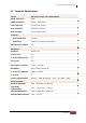
SAS to SAS/SATA II JBOD Subsystem Table of Contents Chapter 1 Introduction.................................................................................................... 3 1.1 Features.............................................................................................................................................................................. 4 1.2 Technical Specifications..................................................................................................................
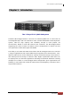
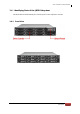
SAS to SAS/SATA II JBOD Subsystem Chapter 1 Introduction The 12 bays EPICa JBOD Subsystem The EPICa EP-2123J/JD-S3S3 is a 19-inch 2U rackmount JBOD unit. It comes with 12 hot-swappable bays and is the Proware's most versatile SAS/SATA II Disk Expansion system, ideal for high capacity and scalability storage in most popular OS environments.
SAS to SAS/SATA II JBOD Subsystem 1.
SAS to SAS/SATA II JBOD Subsystem 1.
SAS to SAS/SATA II JBOD Subsystem 1.
SAS to SAS/SATA II JBOD Subsystem 1.4 Identifying Parts of the JBOD Subsystem The illustrations below identify the various parts of the expansion chassis. 1.4.
SAS to SAS/SATA II JBOD Subsystem 1.4.
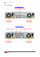
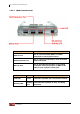
SAS to SAS/SATA II JBOD Subsystem 1.4.3 JBOD Controller Module The EPICa JBOD subsystem includes a single or dual 3Gb SAS-to-SAS/SATA II JBOD Controller Module.
SAS to SAS/SATA II JBOD Subsystem 1.4.3.1 JBOD Controller Panel Part Description SAS In Port Use to connect to SAS HBA or to RAID subsystem’s SAS Expansion Port. SAS Expansion Port Use to connect to the SAS In Port of another JBOD subsystem. RS-232 Port Use to upgrade the firmware of the JBOD controller. Connect the RJ11-to-DB9 serial cable to your system’s serial port. Indicator Color Description Link LED Green Indicates expander has connected or linked.
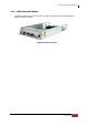
SAS to SAS/SATA II JBOD Subsystem 1.5 Power Supply Fan Module (PSFM) The EPICa JBOD subsystem contains two 400W Power Supply / Fan Modules. All PSFMs are inserted into the rear of the chassis. 1.5.1 PSFM Panel The panel of the Power Supply/Fan Module contains: the Power On/Off Switch, the AC Inlet Plug, and a Power On/Fail Indicator showing the Power Status LED, indicating ready or fail. Each fan within a PSFM is powered independently of the power supply within the same PSFM.
SAS to SAS/SATA II JBOD Subsystem NOTE: Each PSFM has one Power Supply and one Fan. PSFM 1 has Power#1 and Fan#1, and PSFM 2 has Power#2 and Fan#2. When the Power Supply of a PSFM fails, the PSFM need not be removed from the slot if replacement is not yet available. The fan will still work and provide necessary airflow inside the enclosure. In replacing the failed PSFM, refer to section 3.2.2 of this manual.
SAS to SAS/SATA II JBOD Subsystem 1.6 LCD Display Panel 1.6.1 LCD Panel LED Parts Function Power LED Green indicates power is ON. Power Fail LED Fan Fail LED If one of the redundant power supply unit fails, this LED will turn to RED and alarm will sound. Turn RED when fan 1 or 2 fails, or speed is lower than 500 RPM. Over Temperature LED If disk temperatures exceed 60oC, the Over Temperature LED will turn RED and alarm will sound.
SAS to SAS/SATA II JBOD Subsystem 1.6.2 LCD Panel Function Buttons Parts Function Up and Down Arrow buttons Use the Up or Down arrow keys to go through the information on the LCD screen. This is also used to move between each menu. Select button This is used to enter the option you have selected. Exit button 14 User Manual EXIT Press this button to return to the previous menu.
SAS to SAS/SATA II JBOD Subsystem 1.7 Drive Carrier Module The Drive Carrier Module houses a 3.5 inch hard disk drive. It is designed for maximum airflow and incorporates a carrier locking mechanism to prevent unauthorized access to the HDD. 1.7.1 Disk Drive Status Indicators Disk Activity Indicator Disk Status Indicator Part Function Disk Activity Indicator This LED will blink blue when the hard drive is being accessed.
SAS to SAS/SATA II JBOD Subsystem 1.7.2 Drive Carrier Lock Indicator Every Drive Carrier is lockable and is fitted with a lock indicator to indicate whether or not the carrier is locked into the chassis or not. Each carrier is also fitted with an ergonomic handle for easy carrier removal. Drive Carrier is unlocked When the Lock Groove is vertical, then the Drive Carrier is unlocked. Drive Carrier is locked When the Lock Groove is horizontal, this indicates that the Drive Carrier is locked.
SAS to SAS/SATA II JBOD Subsystem Chapter 2 Installation of JBOD Subsystem 2.1 Powering On 1. Plug in the power cords into the AC Power Input Socket located at the rear of the subsystem. NOTE: The subsystem is equipped with redundant, full range power supplies with PFC (power factor correction). The system will automatically select voltage. 2. Turn on each Power On/Off Switch to power on the subsystem. 3. The Power LED on the front panel will turn green.
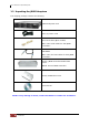
SAS to SAS/SATA II JBOD Subsystem 2.2 Disk Drive Installation This section describes the physical locations of the hard drives supported by the subsystem and give instructions on installing a hard drive. The subsystem supports hot-swapping allowing you to install or replace a hard drive while the subsystem is running. 2.2.1 Installing a SAS Disk Drive in a Disk Tray NOTE: These steps are the same when installing SATA disk drive in Single Controller Mode. 1.
SAS to SAS/SATA II JBOD Subsystem 4. Place the hard drive in the disk tray. Turn the disk tray upside down. Align the four screw holes of the SAS disk drive in the four Hole A of the disk tray. To secure the disk drive into the disk tray, tighten four screws on these holes of the disk tray. Note in the picture below where the screws should be placed in the disk tray holes. Tray Hole A NOTE: All the disk tray holes are labelled accordingly.
SAS to SAS/SATA II JBOD Subsystem 5. Slide the tray into a slot. 6. Press the lever in until you hear the latch click into place. The HDD Fault LED will turn green when the subsystem is powered on and HDD is good. 7. If necessary, lock the Disk Tray by turning the Lock Groove.
SAS to SAS/SATA II JBOD Subsystem 2.2.2 Installing a SATA Disk Drive (Dual JBOD Controller Mode) in a Disk Tray 1. Remove an empty disk tray from the subsystem. 2. Prepare the dongle board and two screws. 3. Place the dongle board in the disk tray. Turn the tray upside down. Align the two screw hole of the dongle board in the two Hole D of the disk tray. Tighten two screws to secure the dongle board into the disk tray.
SAS to SAS/SATA II JBOD Subsystem Tray Hole D NOTE: All the disk tray holes are labelled accordingly. 4. Place the SATA disk drive into the disk tray. Slide the disk drive towards the dongle board.
SAS to SAS/SATA II JBOD Subsystem 5. Turn the disk tray upside down. Align the four screw holes of the SATA disk drive in the four Hole C of the disk tray. To secure the disk drive into the disk tray, tighten four screws on these holes of the disk tray. Note in the picture below where the screws should be placed in the disk tray holes. Tray Hole C NOTE: All the disk tray holes are labelled accordingly. 6. Insert the disk tray into the subsystem.
SAS to SAS/SATA II JBOD Subsystem 2.3 Connecting the JBOD Subsystem 2.3.1 Connecting to SAS HBA The Enclosure supports SAS interface which provides fast 300MB data transfer rate using SAS phy. The package comes with one SAS cable for single JBOD controller module, or two SAS cables for redundant JBOD controller modules. Attach one end of the SAS cable to the SAS IN Port and the other end to the host bus adapter’s (HBA) external SAS connector or to the SAS Switch.
SAS to SAS/SATA II JBOD Subsystem Chapter 3 Maintenance 3.1 Upgrading Firmware Upgrading Firmware Trough Terminal NOTE: It is important to stop I/O access to JBOD subsystem during firmware upgrade. NOTE: Upgrading the firmware must be done from Master JBOD Controller if the JBOD Subsystem has redundant JBOD Controllers. 1. Please use the null modem cable (RJ11 to DB9) and to connect JBOD Monitor Port and PC COM1 Port (or change to other COM Port as necessary). 2. Open Windows HyperTerminal Program.
SAS to SAS/SATA II JBOD Subsystem location. Select “1K Xmodem” Protocol to send firmware file (Only need about 15 seconds to finish sending firmware file. If not, please repeat steps E and F again). NOTE: If the JBOD Subsystem has redundant JBOD Controllers, remove the serial cable (RJ11 to DB9) from RS232 Port of JBOD Controller 1 and insert in the RS232 Port of JBOD Controller 2, and then repeat steps 3 to 6 to upgrade JBOD Controller 2. After upgrading both controllers, power cycle the JBOD Subsystem.
SAS to SAS/SATA II JBOD Subsystem 3.2 Replacing JBOD Subsystem Components 3.2.1 Replacing JBOD Controller Module When replacing a failed JBOD Controller Module, please follow these steps: 1. Loosen the thumbscrews on the sides of the JBOD Controller Module drawer. 2. Use the Controller handle to pull out the defective JBOD Controller Module drawer. 3. Insert and slide the new JBOD Controller Module in.
SAS to SAS/SATA II JBOD Subsystem 3.2.1.1 Replacing Controller Module with Plate Cover When replacing a failed JBOD Controller Module with Plate Cover, please follow these steps: 1. Loosen thumbscrews of the failed JBOD Controller Module drawer. 2. Use the Controller Module handle to remove the failed JBOD Controller Module drawer from the subsystem. 3. Insert the JBOD Controller Plate Cover. JBOD Controller Module Plate Cover 4. Tighten the thumbscrews of the Controller Plate Cover.
SAS to SAS/SATA II JBOD Subsystem 3.2.2 Replacing Power Supply Fan Module When replacing a failed power supply fan module (PSFM), please follow these steps: 1. Turn off the Power On/Off Switch of the failed PSFM. 2. Disconnect the power cord from the AC Inlet Plug of PSFM. 3. Loosen thumbscrews of the PSFM. 4. Use the handle to pull out the defective PSFM. 5. Before inserting the new PSFM, make sure the Power On/Off Switch is on "Off" state. 6. Insert and slide the new PSFM in until it clicks into place.
SAS to SAS/SATA II JBOD Subsystem 3.2.2.1 Replacing Power Supply Fan Module with Plate Cover When replacing a failed power supply fan module (PSFM) with Plate Cover, please follow these steps: 1. Turn off the Power On/Off Switch of the failed PSFM. 2. Disconnect the power cord from the AC Inlet Plug of PSFM. 3. Loosen thumbscrews of the failed PSFM. 4. Pull out the defective PSFM. 5. Insert the PSFM Plate Cover carefully.