PW-RN401/PW-RN401D 150M Wireless N Router Rev: 3.0.
FCC STATEMENT This equipment has been tested and found to comply with the limits for a Class B digital device, pursuant to part 15 of the FCC Rules. These limits are designed to provide reasonable protection against harmful interference in a residential installation. This equipment generates, uses and can radiate radio frequency energy and, if not installed and used in accordance with the instructions, may cause harmful interference to radio communications.
separation distance of at least 20 cm from all persons and must not be co-located or operating in conjunction with any other antenna or transmitter.” CE Mark Warning This is a class B product. In a domestic environment, this product may cause radio interference, in which case the user may be required to take adequate measures.
CONTENTS Package Contents ............................................................................................................................ 1 Chapter 1. Introduction .................................................................................................................. 2 1.1 Overview of the Router ................................................................................................... 2 1.2 Conventions ......................................................................
4.6.5 4.7 4.8 4.9 Wireless Statistics ............................................................................................ 39 DHCP .......................................................................................................................... 39 4.7.1 DHCP Settings ................................................................................................. 40 4.7.2 DHCP Clients List .............................................................................................
4.14.4 Factory Defaults ............................................................................................... 70 4.14.5 Backup & Restore ............................................................................................ 70 4.14.6 Reboot ............................................................................................................. 71 4.14.7 Password ......................................................................................................... 72 4.14.
PW-RN401/PW-RN401D 150M Wireless N Router Package Contents The following items should be found in your package: PW-RN401/PW-RN401D 150M Wireless N Router Power Adapter for PW-RN401/PW-RN401D 150M Wireless N Router Quick Installation Guide Resource CD for PW-RN401/PW-RN401D 150M Wireless N Router, including: This Guide Other Helpful Information Note: Make sure that the package contains the above items.
PW-RN401/PW-RN401D 150M Wireless N Router Chapter 1. Introduction Thank you for choosing the PW-RN401/PW-RN401D 150M Wireless N Router. 1.1 Overview of the Router The PW-RN401/PW-RN401D 150M Wireless N Router integrates 4-port Switch, Firewall, NAT-Router and Wireless AP. The 150M Wireless N Router delivers exceptional range and speed, which can fully meet the need of Small Office/Home Office (SOHO) networks and the users demanding higher networking performance.
PW-RN401/PW-RN401D 150M Wireless N Router 1.2 Conventions The Router or PW-RN401/PW-RN401D mentioned in this guide stands for PW-RN401/PW-RN401D 150M Wireless N Router without any explanation. Note: The two devices of PW-RN401 and PW-RN401D are sharing this User Guide. For simplicity, we will take PW-RN401D for example throughout this Guide. The differences between them are: PW-RN401 Router with one fixed antenna. PW-RN401D Router with one detachable antenna. 1.
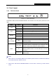
PW-RN401/PW-RN401D 150M Wireless N Router 1.4 Panel Layout 1.4.1 The Front Panel Figure 1-1 Front Panel sketch The Router’s LEDs and the WPS/Reset Button are located on the front panel (View from left to right). Name PWR SYS WLAN WAN, 1,2,3,4 (LAN) WPS Status Indication Off Power is off. On Power is on. On The Router is initializing. Flashing The Router is working properly. Off The Router has a system error. Off The Wireless function is disabled.
PW-RN401/PW-RN401D 1.4.2 150M Wireless N Router The Rear Panel Figure 1-2 Rear Panel sketch The following parts are located on the rear panel (View from left to right). POWER: The Power socket is where you will connect the power adapter. Please use the power adapter provided with this PW-RN401/PW-RN401D 150M Wireless N Router. ON/OFF: The switch for the power. WAN: This WAN port is where you will connect the DSL/cable Modem, or Ethernet.
PW-RN401/PW-RN401D 150M Wireless N Router Chapter 2. Connecting the Router 2.1 System Requirements Broadband Internet Access Service (DSL/Cable/Ethernet) One DSL/Cable Modem that has an RJ45 connector (which is not necessary if the Router is connected directly to the Ethernet.) PCs with a working Ethernet Adapter and an Ethernet cable with RJ45 connectors TCP/IP protocol on each PC Web browser, such as Microsoft Internet Explorer, Mozilla Firefox or Apple Safari 2.
PW-RN401/PW-RN401D 6. 150M Wireless N Router Connect the power adapter to the power socket on the Router, and the other end into an electrical outlet. Press the power switch, and then the router will start to work. 7. Power on your PC and Cable/DSL Modem.
PW-RN401/PW-RN401D 150M Wireless N Router Chapter 3. Quick Installation Guide This chapter will show you how to configure the basic functions of your PW-RN401/PW-RN401D 150M Wireless N Router using Quick Setup Wizard within minutes. 3.1 TCP/IP Configuration The default IP address of the PW-RN401/PW-RN401D 150M Wireless N Router is 192.168.1.1. And the default Subnet Mask is 255.255.255.0. These values can be changed as you desire. In this guide, we use all the default values for description.
PW-RN401/PW-RN401D 150M Wireless N Router Figure 3-1 Success result of Ping command If the result displayed is similar to the Figure 3-2, it means the connection between your PC and the Router is failed. Figure 3-2 Failure result of Ping command Please check the connection following these steps: 1. Is the connection between your PC and the Router correct? Note: The 1/2/3/4 LEDs of LAN ports which you link to on the Router and LEDs on your PC's adapter should be lit. 2.
PW-RN401/PW-RN401D 150M Wireless N Router Note: If the Router's IP address is 192.168.1.1, your PC's IP address must be within the range of 192.168.1.2 ~ 192.168.1.254. 3.2 Quick Installation Guide With a Web-based utility, it is easy to configure and manage the PW-RN401/PW-RN401D 150M Wireless N Router. The Web-based utility can be used on any Windows, Macintosh or UNIX OS with a Web browser, such as Microsoft Internet Explorer, Mozilla Firefox or Apple Safari. 1.
PW-RN401/PW-RN401D 150M Wireless N Router Figure 3-5 Quick Setup 3. Click Next, and then WAN Connection Type page will appear, shown in Figure 3-6. Figure 3-6 WAN Connection Type The Router supports three popular ways PPPoE, Dynamic IP and Static IP to connect to the Internet. Please make sure of what kind of connection type your ISP provides, and then select the very type and click Next to go on configuring. 4. Make sure the cable is securely plugged into the WAN port.
PW-RN401/PW-RN401D 150M Wireless N Router 2) If the connection type is Dynamic IP, the next screen will appear as shown in Figure 3-9. Then you can go on with the wireless configuration. 3) If the connection type is Static IP, the next screen will appear as shown in Figure 3-8. Figure 3-8 Quick Setup - Static IP IP Address - This is the WAN IP address as seen by external users on the Internet (including your ISP). Enter the IP address into the field.
PW-RN401/PW-RN401D 150M Wireless N Router Wireless Radio - Enable or disable the wireless radio choosing from the pull-down list. SSID - Enter a value of up to 32 characters. The same name of SSID (Service Set Identification) must be assigned to all wireless devices in your network. Considering your wireless network security, the default SSID is set to be (XXXXXX indicates the last unique six numbers of each Router’s MAC address). This value is case-sensitive.
PW-RN401/PW-RN401D 150M Wireless N Router If you don’t make any changes on the Wireless page, you will see the Finish page as shown in Figure 3-10. Click the Finish button to finish the Quick Setup. Figure 3-10 Quick Setup - Finish If there is something changed on the Wireless page, you will see the Finish page as shown in Figure 3-11. Click the Reboot button to make your wireless configuration to take effect and finish the Quick Setup.
PW-RN401/PW-RN401D 150M Wireless N Router Chapter 4. Configuring the Router This chapter will show each Web page's key functions and the configuration way. 4.1 Login After your successful login, you will see the thirteen main menus on the left of the Web-based utility. On the right, there are the corresponding explanations and instructions. Figure 4-1 the main menu The detailed explanations for each Web page’s key function are listed below. 4.
PW-RN401/PW-RN401D 150M Wireless N Router Figure 4-2 Router Status 4.3 Quick Setup Please refer to Section 3.2: "Quick Installation Guide". 4.4 WPS This section will guide you to add a new wireless device to an existing network quickly by WPS (Wifi Protected Setup) function.
PW-RN401/PW-RN401D a) 150M Wireless N Router Choose menu “WPS”, you will see the next screen (shown in Figure 4-3 ). Figure 4-3 WPS WPS Status - Enable or disable the WPS function here. Current PIN - The current value of the Router's PIN is displayed here. The default PIN of the Router can be found in the label or User Guide. Restore PIN - Restore the PIN of the Router to its default. Gen New PIN - Click this button, and then you can get a new random value for the Router's PIN.
PW-RN401/PW-RN401D 150M Wireless N Router Note: When press and hold the WPS/Reset Button for more than 5 seconds, you will reset the router. Step 2: Press and hold the WPS Button of the adapter directly for 2 or 3 seconds. Step 3: Wait for a while until the next screen appears. Click Finish to complete the WPS configuration. The WPS Configuration Screen of Wireless Adapter Method Two: Step 1: Press the WPS/Reset Button on the front panel of the Router.
PW-RN401/PW-RN401D 150M Wireless N Router Step 2: For the configuration of the wireless adapter, please choose “Push the button on my access point” in the configuration utility of the WPS as below, and click Next. The WPS Configuration Screen of Wireless Adapter Step 3: Wait for a while until the next screen appears. Click Finish to complete the WPS configuration.
PW-RN401/PW-RN401D 150M Wireless N Router Method Three: Step 1: Keep the default WPS Status as Enabled and click the Add device button in Figure 4-3, then the following screen will appear. Figure 4-4 Add A New Device Step 2: Choose “Press the button of the new device in two minutes” and click Connect. Step 3: For the configuration of the wireless adapter, please choose “Push the button on my access point” in the configuration utility of the WPS as below, and click Next.
PW-RN401/PW-RN401D 150M Wireless N Router The WPS Configuration Screen of Wireless Adapter II. By PIN If the new device supports Wi-Fi Protected Setup and the PIN method, you can add it to the network by PIN with the following two methods. Method One: Enter the PIN into my Router Step 1: Keep the default WPS Status as Enabled and click the Add device button in Figure 4-3, then the following screen will appear.
PW-RN401/PW-RN401D 150M Wireless N Router Step 3: For the configuration of the wireless adapter, please choose “Enter a PIN into my access point or a registrar” in the configuration utility of the WPS as below, and click Next. The WPS Configuration Screen of Wireless Adapter Note: In this example, the default PIN code of this adapter is 16952898 as the above figure shown.
PW-RN401/PW-RN401D 150M Wireless N Router The WPS Configuration Screen of Wireless Adapter Note: The default PIN code of the Router can be found in its label or the WPS configuration screen as Figure 4-3. c) You will see the following screen when the new device successfully connected to the network. Note: 1. The WPS LED on the Router will light green for five minutes if the device has been successfully added to the network. 2.
PW-RN401/PW-RN401D 150M Wireless N Router 4.5 Network Figure 4-5 the Network menu There are three submenus under the Network menu (shown in Figure 4-5): LAN, WAN and MAC Clone. Click any of them, and you will be able to configure the corresponding function. 4.5.1 LAN Choose menu “Network → LAN”, you can configure the IP parameters of the LAN on the screen as below. Figure 4-6 LAN MAC Address - The physical address of the Router, as seen from the LAN. The value can't be changed.
PW-RN401/PW-RN401D 1. 150M Wireless N Router If your ISP provides the DHCP service, please choose Dynamic IP type, and the Router will automatically get IP parameters from your ISP. You can see the page as follows (Figure 4-7): Figure 4-7 WAN – Dynamic IP This page displays the WAN IP parameters assigned dynamically by your ISP, including IP address, Subnet Mask, Default Gateway, etc. Click the Renew button to renew the IP parameters from your ISP. Click the Release button to release the IP parameters.
PW-RN401/PW-RN401D 150M Wireless N Router Get IP with Unicast DHCP - A few ISPs' DHCP servers do not support the broadcast applications. If you cannot get the IP Address normally, you can choose this option. (It is rarely required.) Click the Save button to save your settings. 2. If your ISP provides a static or fixed IP Address, Subnet Mask, Gateway and DNS setting, select Static IP. The Static IP settings page will appear, shown in Figure 4-8.
PW-RN401/PW-RN401D 150M Wireless N Router Figure 4-9 WAN - PPPoE User Name/Password - Enter the User Name and Password provided by your ISP. These fields are case-sensitive. Secondary Connection - It’s available only for PPPoE Connection. If your ISP provides an extra Connection type such as Dynamic/Static IP to connect to a local area network, then you can check the radio button of Dynamic/Static IP to activate this secondary connection.
PW-RN401/PW-RN401D 150M Wireless N Router Note: Only when you have configured the system time on “System Tools → Time settings” page, will the Time-based Connecting function take effect. Connect Manually - You can click the Connect/Disconnect button to connect/disconnect immediately. This mode also supports the Max Idle Time function as Connect on Demand mode.
PW-RN401/PW-RN401D 150M Wireless N Router ISP Specified IP Address - If your ISP does not automatically assign IP addresses to the Router during login, please click “Use IP address specified by ISP” check box and enter the IP address provided by your ISP in dotted-decimal notation. Detect Online Interval - The Router will detect Access Concentrator online at every interval. The default value is “0”. You can input the value between “0” and “120”. The value “0” means no detect.
PW-RN401/PW-RN401D 150M Wireless N Router 4.6 Wireless Figure 4-12 Wireless menu There are five submenus under the Wireless menu (shown in Figure 4-12): Wireless Settings, Wireless Security, Wireless MAC Filtering, Wireless Advanced and Wireless Statistics. Click any of them, and you will be able to configure the corresponding function. 4.6.1 Wireless Settings Choose menu “Wireless → Wireless Settings”, you can configure the basic settings for the wireless network on this page.
PW-RN401/PW-RN401D 150M Wireless N Router Region - Select your region from the pull-down list. This field specifies the region where the wireless function of the Router can be used. It may be illegal to use the wireless function of the Router in a region other than one of those specified in this field. If your country or region is not listed, please contact your local government agency for assistance.
PW-RN401/PW-RN401D 150M Wireless N Router Enable SSID Broadcast - When wireless clients survey the local area for wireless networks to associate with, they will detect the SSID broadcast by the Router. If you select the Enable SSID Broadcast checkbox, the Wireless Router will broadcast its name (SSID) on the air. Enable WDS - Check this box to enable WDS. With this function, the Router can bridge two or more Wlans.
PW-RN401/PW-RN401D 150M Wireless N Router Figure 4-15 Wireless Security Disable Security - If you do not want to use wireless security, check this radio button. But it’s strongly recommended to choose one of the following modes to enable security. WEP - It is based on the IEEE 802.11 standard. If you check this radio button, the page will appear as shown in Figure 4-16. Figure 4-16 Type - you can choose the type for the WEP security on the pull-down list.
PW-RN401/PW-RN401D 150M Wireless N Router WEP Key Format - Hexadecimal and ASCII formats are provided here. Hexadecimal format stands for any combination of hexadecimal digits (0-9, a-f, A-F) in the specified length. ASCII format stands for any combination of keyboard characters in the specified length. WEP Key - Select which of the four keys will be used and enter the matching WEP key that you create. Make sure these values are identical on all wireless stations in your network.
PW-RN401/PW-RN401D 150M Wireless N Router WPA-PSK/WPA2-PSK - It’s the WPA/WPA2 authentication type based on pre-shared passphrase. If you check this radio button, the page will appear as shown in Figure 4-18 Figure 4-18 Version - you can choose the version of the WPA-PSK security on the drop-down list. The default setting is Automatic, which can select WPA-PSK (Pre-shared key of WPA) or WPA2-PSK (Pre-shared key of WPA) automatically based on the wireless station's capability and request.
PW-RN401/PW-RN401D Status - The status of this entry, either Enabled or Disabled. Description - A simple description of the wireless station. 150M Wireless N Router To Add a Wireless MAC Address filtering entry, click the Add New… button. The "Add or Modify Wireless MAC Address Filtering entry" page will appear, shown in Figure 4-20: Figure 4-20 Add or Modify Wireless MAC Address Filtering entry To add a MAC Address Filtering entry, follow these instructions: 1.
PW-RN401/PW-RN401D 150M Wireless N Router For example: If you desire that the wireless station A with MAC address 00-0A-EB-B0-00-0B and the wireless station B with MAC address 00-0A-EB-00-07-5F are able to access the Router, but all the other wireless stations cannot access the Router, you can configure the Wireless MAC Address Filtering list by following these steps: 1. Click the Enable button to enable this function. 2.
PW-RN401/PW-RN401D 150M Wireless N Router Figure 4-21 Wireless Advanced Beacon Interval - Enter a value between 20-1000 milliseconds for Beacon Interval here. The beacons are the packets sent by the Router to synchronize a wireless network. Beacon Interval value determines the time interval of the beacons. The default value is 100. RTS Threshold - Here you can specify the RTS (Request to Send) Threshold.
PW-RN401/PW-RN401D 150M Wireless N Router Note: If you are not familiar with the setting items in this page, it's strongly recommended to keep the provided default values; otherwise it may result in lower wireless network performance. 4.6.5 Wireless Statistics Choose menu “Wireless → Wireless Statistics”, you can see the MAC Address, Current Status, Received Packets and Sent Packets for each connected wireless station.
PW-RN401/PW-RN401D 150M Wireless N Router There are three submenus under the DHCP menu (shown in Figure 4-23), DHCP Settings, DHCP Clients List and Address Reservation. Click any of them, and you will be able to configure the corresponding function. 4.7.1 DHCP Settings Choose menu “DHCP → DHCP Settings”, you can configure the DHCP Server on the page as shown in Figure 4-24.
PW-RN401/PW-RN401D 150M Wireless N Router Primary DNS - (Optional.) Input the DNS IP address provided by your ISP or consult your ISP. Secondary DNS - (Optional.) Input the IP address of another DNS server if your ISP provides two DNS servers. Note: To use the DHCP server function of the Router, you must configure all computers on the LAN as "Obtain an IP Address automatically". 4.7.
PW-RN401/PW-RN401D 150M Wireless N Router Figure 4-26 Address Reservation MAC Address - The MAC address of the PC for which you want to reserve an IP address. Reserved IP Address - The IP address reserved for the PC by the Router. Status - The status of this entry, either Enabled or Disabled. To Reserve an IP address: 1. Click the Add New… button. Then Figure 4-27 will pop-up. 2. Enter the MAC address (in XX-XX-XX-XX-XX-XX format.
PW-RN401/PW-RN401D 150M Wireless N Router 4.8 Forwarding Figure 4-28 The Forwarding menu There are four submenus under the Forwarding menu (shown in Figure 4-28): Virtual Servers, Port Triggering, DMZ and UPnP. Click any of them, and you will be able to configure the corresponding function. 4.8.1 Virtual Servers Choose menu “Forwarding → Virtual Servers”, you can view and add virtual servers in the screen as shown in Figure 4-29.
PW-RN401/PW-RN401D 2. 150M Wireless N Router Select the service port you want to use from the Common Service Port list. If the Common Service Port list does not have the service that you want to use, type the service port number or service port range in the Service Port box. 3. Type the IP Address of the computer in the IP Address box. 4. Select the protocol used for this application, either TCP, UDP, or All. 5. Select the Enable to enable the virtual server. 6. Click the Save button.
PW-RN401/PW-RN401D 4.8.2 150M Wireless N Router Port Triggering Choose menu “Forwarding → Port Triggering”, you can view and add port triggering in the screen as shown in Figure 4-31. Some applications require multiple connections, like Internet games, video conferencing, Internet calling and so on. These applications cannot work with a pure NAT Router. Port Triggering is used for some of these applications that can work with an NAT Router.
PW-RN401/PW-RN401D 2. 150M Wireless N Router Select a common application from the Common Applications drop-down list, then the Trigger Port field and the Incoming Ports field will be automatically filled. If the Common Applications do not have the application you need, enter the Trigger Port and the Incoming Ports manually. 3. Select the protocol used for Trigger Port from the Trigger Protocol drop-down list, either TCP, UDP, or All. 4.
PW-RN401/PW-RN401D 4.8.3 150M Wireless N Router DMZ Choose menu “Forwarding → DMZ”, you can view and configure DMZ host in the screen as shown in Figure 4-33. The DMZ host feature allows one local host to be exposed to the Internet for a special-purpose service such as Internet gaming or videoconferencing. DMZ host forwards all the ports at the same time.
PW-RN401/PW-RN401D 150M Wireless N Router Current UPnP Settings List - This table displays the current UPnP information. App Description - The description provided by the application in the UPnP request. External Port - The external port the Router opens for the application. Protocol - The type of protocol the Router opens for the application. Internal Port - The Internal port the Router opens for local host.
PW-RN401/PW-RN401D 150M Wireless N Router Figure 4-36 Firewall Settings Enable Firewall - the general firewall switch is on or off. Enable IP Address Filtering - set IP Address Filtering is enabled or disabled. There are two default filtering rules of IP Address Filtering, either Allow or Deny passing through the router. Enable Domain Filtering - set Domain Filtering is enabled or disabled. Enable MAC Filtering - set MAC Address Filtering is enabled or disabled.
PW-RN401/PW-RN401D 150M Wireless N Router Figure 4-37 IP Filtering To disable the IP Address Filtering feature, keep the default setting, Disabled. To set up an IP Address Filtering entry, click Enable Firewall and Enable IP Address Filtering on the Firewall page, and click the Add New… button. The page "Add or Modify an IP Address Filtering entry" will appear shown in.
PW-RN401/PW-RN401D 150M Wireless N Router 3. LAN Port - Enter a LAN Port or a range of LAN ports in the field. For example, 1030 - 2000. Keep the field open, which means all LAN ports have been put into the field. 4. WAN IP Address - Enter a WAN IP Address or a range of WAN IP Addresses in the field, in dotted-decimal notation format. For example, 61.145.238.6 – 61.145.238.47. Keep the field open, which means all WAN IP Addresses have been put into the field. 5.
PW-RN401/PW-RN401D 4.9.3 150M Wireless N Router Domain Filtering The Domain Filtering page allows you to control access to certain websites on the Internet by specifying their domains or key words. The Domain filtering is set on the page shown in.Figure 4-39 Figure 4-39 Domain Filtering Before adding a Domain Filtering entry, you must ensure that Enable Firewall and Enable Domain Filtering have been selected on the Firewall page. To Add a Domain filtering entry, click the Add New… button.
PW-RN401/PW-RN401D 150M Wireless N Router 1. Click the Modify in the entry you want to modify. If you want to delete the entry, click the Delete. 2. Modify the information. 3. Click the Save button. Click the Enabled All button to make all entries enabled. Click the Disabled All button to make all entries disabled. Click the Delete All button to delete all entries Click the Next button to go to the next page and the Previous button to return to the previous page.
PW-RN401/PW-RN401D 150M Wireless N Router the Add New… button. The page "Add or Modify a MAC Address Filtering entry" will appear, shown inFigure 4-42. Figure 4-42 Add or Modify a MAC Address Filtering entry To add or modify a MAC Address Filtering entry, follow these instructions: 1. Enter the appropriate MAC Address into the MAC Address field. The format of the MAC Address is XX-XX-XX-XX-XX-XX 00-0E-AE-B0-00-0B. (X is any hexadecimal digit). For 2.
PW-RN401/PW-RN401D 150M Wireless N Router these PC(s) with effective rules to access the Internet" on the Firewall page and the following MAC address filtering list on this page: 4.9.5 Remote Management Choose menu “Security → Remote Management”, you can configure the Remote Management function in the screen as shown inFigure 4-43. This feature allows you to manage your Router from a remote location via the Internet.
PW-RN401/PW-RN401D 4.9.6 150M Wireless N Router Advanced Security Choose menu “Security → Advanced Security”, you can protect the Router from being attacked by TCP-SYN Flood, UDP Flood and ICMP-Flood in the screen as shown inFigure 4-44. Figure 4-44 Advanced Security Packets Statistics Interval (5~60) - The default value is 10. Select a value between 5 and 60 seconds from the drop-down list. The Packets Statistics Interval value indicates the time section of the packets statistics.
PW-RN401/PW-RN401D 150M Wireless N Router UDP-FLOOD Packets Threshold (5~3600) - The default value is 500. Enter a value between 5 ~ 3600. When the current UPD-FLOOD Packets number is beyond the set value, the Router will startup the blocking function immediately. Enable TCP-SYN-FLOOD Attack Filtering - Enable or Disable the TCP-SYN-FLOOD Attack Filtering. TCP-SYN-FLOOD Packets Threshold (5~3600) - The default value is 50. Enter a value between 5 ~ 3600.
PW-RN401/PW-RN401D 150M Wireless N Router Figure 4-46 Add or Modify a Static Route Entry 2. Enter the following data. Destination IP Address - The Destination IP Address is the address of the network or host that you want to assign to a static route. Subnet Mask - The Subnet Mask determines which portion of an IP Address is the network portion, and which portion is the host portion.
PW-RN401/PW-RN401D 150M Wireless N Router 4.11 Bandwidth Control You can configure the Bandwidth control function on this page shown inFigure 4-47: Figure 4-47 Bandwidth Control Enable IP QoS - Enable or disable the function of IP QoS. Choose BandWidth Type - Select the network connection type from the drop-down list. Bandwidth Apply - The bandwidth you get. If you are not clear about that, please contact with your ISP for help. IP Range - IP range of this entry.
PW-RN401/PW-RN401D 2. 150M Wireless N Router Please choose the Network Connection Type and set the bandwidth according to your Network. If you are not clear about that, please contact with your ISP for help. 3. If no IP QoS item is enabled, the Bandwidth Apply won't be effective. 4. IP address range for different entries could not have intersection with each other. 5. After the configurations, click the Save button for the change to take effect. 4.
PW-RN401/PW-RN401D 150M Wireless N Router Figure 4-50 IP & MAC Binding Settings To add IP & MAC Binding entries, follow the steps below. 1. Click the Add New... button as shown in Figure 4-49. 2. Enter the MAC Address and IP Address. 3. Select the Bind checkbox. 4. Click the Save button to save it. To modify or delete an existing entry, follow the steps below. 1. Find the desired entry in the table. 2. Click Modify or Delete as desired on the Modify column.
PW-RN401/PW-RN401D 150M Wireless N Router 4.12.2 ARP List To manage the computer, you could observe the computers in the LAN by checking the relationship of MAC address and IP address on the ARP list, and you could configure the items on the ARP list also. This page displays the ARP List; it shows all the existing IP & MAC Binding entries as shown in Figure 4-52. Figure 4-52 ARP List MAC Address - The MAC address of the controlled computer in the LAN.
PW-RN401/PW-RN401D 150M Wireless N Router name no matter what your IP address is. Before using this feature, you need to sign up for DDNS service providers such as www.dyndns.org, or www.no-ip.com. The Dynamic DNS client service provider will give you a password or key. 4.13.1 Dyndns.org DDNS If the dynamic DNS Service Provider your select is www.dyndns.org, the page will appear as shown in Figure 4-53. Figure 4-53 Dyndns.org DDNS Settings To set up for DDNS, follow these instructions: 1.
PW-RN401/PW-RN401D 150M Wireless N Router 4.13.2 Oray.net DDNS If your selected dynamic DNS Service Provider is www.oray.net, the page will appear as shown in Figure 4-54. Figure 4-54 Oray.net DDNS Settings To set up for DDNS, follow these instructions: 1. Type the User Name for your DDNS account. 2. Type the Password for your DDNS account. 3. Click the Login button to login the DDNS service. Connection Status - The status of the DDNS service connection is displayed here.
PW-RN401/PW-RN401D 150M Wireless N Router Figure 4-55 Comexe.cn DDNS settings To set up for DDNS, follow these instructions: 1. 2. 3. Type the domain names your dynamic DNS service provider gave. Type the User Name for your DDNS account. Type the Password for your DDNS account. 4. Click the Login button to login to the DDNS service. Connection Status -The status of the DDNS service connection is displayed here. Click Logout to logout of the DDNS service.
PW-RN401/PW-RN401D 150M Wireless N Router 4.14 System Tools Figure 4-56 The System Tools menu Choose menu “System Tools”, you can see the submenus under the main menu: Time Settings, Diagnostic, Firmware Upgrade, Factory Defaults, Backup & Restore, Reboot, Password, System Log and Statistics. Click any of them, and you will be able to configure the corresponding function. The detailed explanations for each submenu are provided below. 4.14.
PW-RN401/PW-RN401D 150M Wireless N Router To set time manually, follow the steps below: 1. Select your local time zone. 2. Enter the Date in Month/Day/Year format. 3. Enter the Time in Hour/Minute/Second format. 4. Click Save. For automatic time synchronization: 1. Enter the address of the NTP Server Prior. 2. Click the Get GMT button to get GMT time from Internet if you have connected to Internet. Note: This setting will be used for some time-based functions such as firewall.
PW-RN401/PW-RN401D 150M Wireless N Router Figure 4-58 Diagnostic Tools Diagnostic Tool - Check the radio button to select one diagnostic too. Ping - This diagnostic tool troubleshoots connectivity, reachability, and name resolution to a given host or gateway. Traceroute - This diagnostic tool tests the performance of a connection. Note: You can use ping/traceroute to test both numeric IP address or domain name.
PW-RN401/PW-RN401D 150M Wireless N Router Click Start to check the connectivity of the Internet. The Diagnostic Results page displays the result of diagnosis. If the result is similar to the following screen, the connectivity of the Internet is fine. Figure 4-59 Diagnostic Results Note: Only one user can use this tool at one time. Options “Number of Pings”, “Ping Size” and “Ping Timeout” are used for Ping function. Option “Tracert Hops” are used for Tracert function. 4.14.
PW-RN401/PW-RN401D 150M Wireless N Router Note: 1. New firmware versions are posted at our website and can be downloaded for free. There is no need to upgrade the firmware unless the new firmware has a new feature you want to use. However, when experiencing problems caused by the Router rather than the configuration, you can try to upgrade the firmware. 2.
PW-RN401/PW-RN401D 150M Wireless N Router Figure 4-62 Backup & Restore Configuration Click the Backup button to save all configuration settings as a backup file in your local computer. To upgrade the Router's configuration, follow these instructions. Click the Browse… button to locate the update file for the Router, or enter the exact path to the Setting file in the text box. Click the Restore button. Note: The current configuration will be covered by the uploading configuration file.
PW-RN401/PW-RN401D 150M Wireless N Router 4.14.7 Password Choose menu “System Tools → Password”, you can change the factory default user name and password of the Router in the next screen as shown in Figure 4-64. Figure 4-64 Password It is strongly recommended that you should change the factory default user name and password of the Router, because all users who try to access the Router's Web-based utility or Quick Setup will be prompted for the Router's default user name and password.
PW-RN401/PW-RN401D 150M Wireless N Router Figure 4-65 System Log The router can keep logs of all traffic. You can query the logs to find what happened to the router. Click the Refresh button to refresh the logs. Click the Clear All button to clear all the logs. 4.14.9 Statistics Choose menu “System Tools → Statistics”, you can view the network traffic of each PC on the LAN, including total traffic and the value of the last Packets Statistic interval in seconds.
PW-RN401/PW-RN401D 150M Wireless N Router Packets Statistics Interval (5-60) - The default value is 10. Select a value between 5 and 60 seconds in the pull-down list. The Packets Statistic interval indicates the time section of the packets statistic. Select the Auto-refresh checkbox to refresh automatically. Click the Refresh button to refresh the page. Sorted Rules - Choose how displayed statistics are sorted. Click Reset All to reset the values of all the entries to zero.
PW-RN401/PW-RN401D 150M Wireless N Router Appendix A: FAQ 1. How do I configure the Router to access the Internet by ADSL users? 1) First, configure the ADSL Modem configured in RFC1483 bridge model. 2) Connect the Ethernet cable from your ADSL Modem to the WAN port on the Router. The telephone cord plugs into the Line port of the ADSL Modem. 3) Log in to the Router, click the “Network” menu on the left of your browser, and click "WAN" submenu.
PW-RN401/PW-RN401D 2. 150M Wireless N Router How do I configure the Router to access the Internet by Ethernet users? 1) Log in to the Router, click the “Network” menu on the left of your browser, and click "WAN" submenu. On the WAN page, select “Dynamic IP” for "WAN Connection Type", finish by clicking Save. 2) Some ISPs require that you register the MAC Address of your adapter, which is connected to your cable/DSL Modem during installation.
PW-RN401/PW-RN401D 150M Wireless N Router Figure A-4 Virtual Servers Figure A-5 Add or Modify a Virtual server Entry Note: Your opposite side should call your WAN IP, which is displayed on the “Status” page. 4) How to enable DMZ Host: Log in to the Router, click the “Forwarding” menu on the left of your browser, and click "DMZ" submenu. On the "DMZ" page, click Enable radio button and type your IP address into the “DMZ Host IP Address” field, using 192.168.1.
PW-RN401/PW-RN401D 1) 150M Wireless N Router Because the WEB Server port 80 will interfere with the WEB management port 80 on the Router, you must change the WEB management port number to avoid interference. 2) To change the WEB management port number: Log in to the Router, click the “Security” menu on the left of your browser, and click "Remote Management" submenu. On the "Remote Management" page, type a port number except 80, such as 88, into the "Web Management Port" field.
PW-RN401/PW-RN401D 150M Wireless N Router Figure A-9 Add or Modify a Virtual server Entry 5. The wireless stations cannot connect to the Router. 1) Make sure the "Enable Wireless Router Radio" is checked. 2) Make sure that the wireless stations' SSID accord with the Router's SSID. 3) Make sure the wireless stations have right KEY for encryption when the Router is encrypted. 4) If the wireless connection is ready, but you can’t access the Router, check the IP Address of your wireless stations.
PW-RN401/PW-RN401D 150M Wireless N Router Appendix B: Configuring the PC In this section, we’ll introduce how to install and configure the TCP/IP correctly in Windows XP. First make sure your Ethernet Adapter is working, refer to the adapter’s manual if necessary. 1. Configure TCP/IP component 1) On the Windows taskbar, click the Start button, and then click Control Panel. 2) Click the Network and Internet Connections icon, and then click on the Network Connections tab in the appearing window.
PW-RN401/PW-RN401D 150M Wireless N Router Figure B-2 5) The following TCP/IP Properties window will display and the IP Address tab is open on this window by default.
PW-RN401/PW-RN401D 150M Wireless N Router Figure B-3 Note: For Windows 98 OS or before, the PC and Router may need to be restarted. Setting IP address manually 1 Select Use the following IP address radio button. And the following items available. 2 If the Router's LAN IP address is 192.168.1.1, specify the IP address as 192.168.1.x (x is from 2 to 254), and the Subnet mask as 255.255.255.0. 3 Type the Router’s LAN IP address (the default IP is 192.168.1.1) into the Default gateway field.
PW-RN401/PW-RN401D Figure B-4 Now, click OK to keep your settings.
PW-RN401/PW-RN401D 150M Wireless N Router Appendix C: Specifications General Standards IEEE 802.3, 802.3u, 802.11b, 802.11g Compatible with 802.
PW-RN401/PW-RN401D 150M Wireless N Router Appendix D: Glossary 802.11b - The 802.11b standard specifies a wireless networking at 11 Mbps using direct-sequence spread-spectrum (DSSS) technology and operating in the unlicensed radio spectrum at 2.4GHz, and WEP encryption for security. 802.11b networks are also referred to as Wi-Fi networks. 802.
PW-RN401/PW-RN401D 150M Wireless N Router WEP (Wired Equivalent Privacy) - A data privacy mechanism based on a 64-bit or 128-bit or 152-bit shared key algorithm, as described in the IEEE 802.11 standard. Wi-Fi - A trade name for the 802.11b wireless networking standard, given by the Wireless Ethernet Compatibility Alliance (WECA, see http://www.wi-fi.net), an industry standards group promoting interoperability among 802.11b devices.