
User guide


ASUS PTGD1-LA (Grouper-GL8E) motherboardASUS PTGD1-LA (Grouper-GL8E) motherboard
ASUS PTGD1-LA (Grouper-GL8E) motherboardASUS PTGD1-LA (Grouper-GL8E) motherboard
ASUS PTGD1-LA (Grouper-GL8E) motherboard
1111
1111
11
6.26.2
6.26.2
6.2
Internal connectorsInternal connectors
Internal connectorsInternal connectors
Internal connectors
This section describes and illustrates the internal connectors on the
motherboard.
1.1.
1.1.
1.
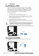
Floppy disk drive connector (34-1 pin FLOPPY)Floppy disk drive connector (34-1 pin FLOPPY)
Floppy disk drive connector (34-1 pin FLOPPY)Floppy disk drive connector (34-1 pin FLOPPY)
Floppy disk drive connector (34-1 pin FLOPPY)
This connector supports the provided floppy drive ribbon cable. After
connecting one end to the motherboard, connect the other end to the
floppy drive. (Pin 5 is removed to prevent incorrect insertion when using
ribbon cables with pin 5 plug).
PTGD1-LA
NOTE: Orient the red markings o
n
the floppy ribbon cable to PIN 1.
PTGD1-LA Floppy Disk Drive Connector
FLOPPY
PIN 1
2.2.
2.2.
2.
IDE connector (40-1 pin IDE)IDE connector (40-1 pin IDE)
IDE connector (40-1 pin IDE)IDE connector (40-1 pin IDE)
IDE connector (40-1 pin IDE)
This connector supports the provided UltraDMA100/66 IDE hard disk
ribbon cable. Connect the cable’s blue connector to the IDE connector,
then connect the gray connector to the UltraDMA100/66 slave device
(hard disk drive) and the black connector to the UltraDMA100/66 master
device.
•
Pin 20 on the IDE connector is removed to match the covered hole
on the UltraDMA cable connector. This prevents incorrect orientation
when you connect the cables.
•
The hole near the blue connector on the UltraDMA100/66 cable is
intentional.
PTGD1-LA
PTGD1-LA IDE Connector
NOTE: Orient the red marking
s
(usually zigzag) on the IDE
ribbon cable to PIN 1.
IDE
PIN 1