User’s Manual and Operating Instructions Model Numbers: PT-18W-DDF-A, PT-20F-DDF-A, PT-20S-DDF, PT-24O-DDF, PT-24-DDF-L, PT-30-DDF, PT-30P-DDF-L &0 / ,6 7( ' READ AND SAVE THESE INSTRUCTIONS IMPORTANT: Read and understand all of the instructions in this manual before assembling, starting, or servicing the fan. Improper use of this fan can cause serious injury. Keep this manual for future reference. For General Ventilating Use Only. Do Not Use To Exhaust Hazardous Or Explosive Materials And Vapors.
User’s Manual and Operating Instructions Table of Contents Safety Information................................................................................................................................. 3 Notes Page............................................................................................................................................4 Troubleshooting Guide........................................................................................................................
NEVER LEAVE A FAN UNATTENDED WHILE OPERATING OR WHILE CONNECTED TO A POWER SOURCE Safety Information IMPORTANT: READ ALL INSTRUCTIONS CAREFULLY BEFORE ASSEMBLY, SERVICE OR USE OF THIS FAN. FAILURE TO COMPLY WITH THESE INSTRUCTIONS COULD RESULT IN SERIOUS PERSONAL INJURY AND / OR PROPERTY DAMAGE. THIS IS A FAN - NOT A TOY! WARNING TO REDUCE THE RISK OF PERSONAL INJURY AND ELECTRIC SHOCK, FANS SHOULD NOT BE PLAYED WITH OR PLACED WHERE SMALL CHILDREN CAN REACH IT.
NEVER LEAVE A FAN UNATTENDED WHILE OPERATING OR WHILE CONNECTED TO A POWER SOURCE NOTES __________________________________________________________________________________________ __________________________________________________________________________________________ __________________________________________________________________________________________ __________________________________________________________________________________________ ___________________________________________________________
NEVER LEAVE A FAN UNATTENDED WHILE OPERATING OR WHILE CONNECTED TO A POWER SOURCE Wall Mount Installation 18” WALL FAN: PT-18W-DDF-A WARNING The installer MUST be certain that the support bracket is mounted to a minimum of a 2x4” stud, and that it is able to support 50 pounds continuously. 1. Attach fan to wall or ceiling using Upper Bracket (Item #6). 2. Be sure Upper Bracket (Item #6) is attached to a suitable beam when hanging. Tools Needed: - 10mm Adjustable Wrench.
NEVER LEAVE A FAN UNATTENDED WHILE OPERATING OR WHILE CONNECTED TO A POWER SOURCE 20” FLOOR FAN: PT-20F-DDF-A Installation and Assembly 1. Remove 1 screw from each Frame Support L and R (Items #7* and #19*). 4. Place the fan on level ground in a safe, desired position then connect to an approved power source. 2. Slide Frame Support L and Frame Support R into Support Frame (Item #21*) and line up holes for screw. Tools Needed: - Phillips head screwdriver. -10 mm adjustable wrench. 3.
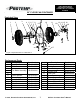
NEVER LEAVE A FAN UNATTENDED WHILE OPERATING OR WHILE CONNECTED TO A POWER SOURCE 20” FLOOR FAN CONTINUED Exploded View 1 2 3 4 5 6 7 8 10 9 11 14 15 16 12 13 24 21 19 18 20 23 22 17 Figure 4: Exploded View of PT-20F-DDF-A Replacement Parts Item # 1 2 3 4 5 6 7 8 9 10 11 12 Description Part Number Item # Description Part Number Logo Plate Front Guard 95-043-0405 95-032-0160 Fan Blade Assembly 95-003-0616 Frame Washer Frame-Support L Main Circle Tube Top Washer Rear Guard Motor Sw
NEVER LEAVE A FAN UNATTENDED WHILE OPERATING OR WHILE CONNECTED TO A POWER SOURCE 20” SHOP FAN: PT-20S-DDF Installation and Assembly 1. Remove Knob Screw (Item #15*) and Wing Nut (Item #14*) from top of Post. 5. Place the fan on level ground in a safe, desired position then connect to an approved power source. 2. Slide Connector Bracket (Item #4*) onto top of post. 6. Set desired tripod stand height following “Tripod Operation Instructions” below. 3.
NEVER LEAVE A FAN UNATTENDED WHILE OPERATING OR WHILE CONNECTED TO A POWER SOURCE 20” SHOP FAN CONTINUED - OPTIONAL CEILING MOUNT Figure 5: Optional Ceiling Mount Figure 6: Optional Ceiling Mount Figure 7: Optional Ceiling Mount Figure 8: Optional Ceiling Mount © 2014, Pinnacle Products International, Inc.
NEVER LEAVE A FAN UNATTENDED WHILE OPERATING OR WHILE CONNECTED TO A POWER SOURCE 20” SHOP FAN CONTINUED Exploded View 1 2 3 4 5 14 6 7 15 8 9 10 11 13 12 16 Figure 9: Exploded View of PT-20S-DDF Replacement Parts Item # Description 1 Logo Plate 2 Front Guard 3 Fan Blade Assembly 4 Frame 5 Rear Guard 6 Motor 7 Switch Holder 8 Power Cord Part Number 95-043-0420 95-032-0185 95-003-0616 95-001-0500 95-032-0285 95-030-0525 95-031-0335 95-026-0270 © 2014, Pinnacle Products International, Inc.
NEVER LEAVE A FAN UNATTENDED WHILE OPERATING OR WHILE CONNECTED TO A POWER SOURCE 24” BARREL FAN: PT-24-DDF-L Installation and Assembly NOTE: This model CAN NOT be wall mounted. 1. Place the fan on level ground in a safe, desired position then connect to an approved power source.
NEVER LEAVE A FAN UNATTENDED WHILE OPERATING OR WHILE CONNECTED TO A POWER SOURCE 24’’ OMNI DIRECTIONAL FAN: PT-24O-DDF Installation and Assembly 1. Place the fan on level ground in a safe, desired position then connect to an approved power source.
NEVER LEAVE A FAN UNATTENDED WHILE OPERATING OR WHILE CONNECTED TO A POWER SOURCE 24” OMNI FAN - OPTIONAL WALL MOUNT Wall Mount Installation WARNING The installer MUST be 1. Attach Wall Mount (Item #17*) to wood stud as shown below. 2. Slide Wall Bracket L (Item #25*) and Wall Bracket R (Item #26*) on Large Base (Item #23*) onto Wall Mount. certain that the support bracket is mounted to a minimum of a 2x4” stud, and that it is able to support 105 pounds continuously. Tools Needed -Flat head Screw Driver.
NEVER LEAVE A FAN UNATTENDED WHILE OPERATING OR WHILE CONNECTED TO A POWER SOURCE 30” FLOOR FAN: PT-30-DDF Installation and Assembly NOTE: This fan uses a folding wheel design. For quick assembly, simply swing the wheels out and snap to lock in place. 1. Place the fan on level ground in a safe, desired position then connect to an approved power source.
NEVER LEAVE A FAN UNATTENDED WHILE OPERATING OR WHILE CONNECTED TO A POWER SOURCE 30” FLOOR FAN - OPTIONAL CEILING MOUNT Ceiling Mount Installation WARNING The installer MUST be MOUNTING BRACKET INSTALLATION: 1. Remove Wheel Frame (Item #15) 2. Attach Cart Frame to Ceiling beam using U-bolts (Item #5). 3. Assemble and attach Ceiling Mount Assembly as shown in Figure 15 below. certain that the support bracket is mounted to a minimum of a 2x4” stud, and that it is able to support 105 pounds continuously.
NEVER LEAVE A FAN UNATTENDED WHILE OPERATING OR WHILE CONNECTED TO A POWER SOURCE 30” FLOOR FAN - OPTIONAL CEILING MOUNT CONTINUED Ceiling Mount Installation 1. 2. 3. 4. 5. SAFETY CABLE INSTALLATION: After the fan is securely mounted, feed the safety cable between one of the swivel brackets as shown in Figure 15. Pull safety cable through and secure cable with safety cable U-bolt as shown in Figure 17. Take other end of cable and wrap around beam Secure cable loop as shown in step 2.
NEVER LEAVE A FAN UNATTENDED WHILE OPERATING OR WHILE CONNECTED TO A POWER SOURCE 30” PEDESTAL FAN: PT-30P-DDF-L 1. Mount the lower support pole to the base Installation and Assembly using four (4) 20 mm cap bolts. Secure tightly with four (4) nuts. Tools Needed: Pliers Phillips head screwdriver Flat head screwdriver 10mm / adjustable wrench 2. Remove the screw at the top of the lower support pole. 3. Slide upper support pole into lower support pole.
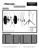
NEVER LEAVE A FAN UNATTENDED WHILE OPERATING OR WHILE CONNECTED TO A POWER SOURCE 30” PEDESTAL FAN Exploded View 11 10 9 8 7 6 5 4 3 2 1 Figure 20: Exploded View of PT-30P-DDF-L Replacement Parts Item # Description 1 Base 2 Lower Support Pole 3 Locking Knob Screw 4 Locking Collar 5 Locking Collar Nut 6 Upper Support Pole Part Number Item # 95-024-1000 7 95-017-1000 8 95-015-1003 9 95-017-1001 10 95-017-1002 11 95-017-1003 12 © 2014, Pinnacle Products International, Inc.
NEVER LEAVE A FAN UNATTENDED WHILE OPERATING OR WHILE CONNECTED TO A POWER SOURCE Troubleshooting Guide Problem Fan does not operate Reduced Air Flow Humming sound but no operation Possible Cause Corrective Action 1. No power Inspect power cord for damage. Be sure unit is plugged in and turned on. 2. Bad motor Replace motor 1. Obstruction Turn off and unplug fan. Remove guard and make sure nothing is obstructing the fan blades. 2.
NEVER LEAVE A FAN UNATTENDED WHILE OPERATING OR WHILE CONNECTED TO A POWER SOURCE 1 YEAR LIMITED WARRANTY Pinnacle Products International, Inc. warrants this product to the original retail purchaser only, to be free from defects in material and workmanship for a period of one (1) year from the date of initial purchase. This product must be properly installed, maintained and operated in accordance with the instructions provided. Pinnacle Products International, Inc.