
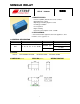
Specification Sheet

2
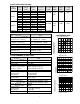
6. COIL DATA CHART (AT20
C)
Coil
Sensitivity
Coil
Voltage
Code
Nominal
Voltage
(VDC)
Nominal
Current
(mA)
Coil
Resistance
(
Ω
)
±
10%
Power
Consumpti
on (W)
Pull-In
Voltage
(VDC)
Drop-Out
Voltage
(VDC)
Max-Allowab
le Voltage
(VDC)
03 3 120 25
05 5 71.4 70
06 6 60 100
09 9 40.9 220
12 12 30 400
SRC-L
24 24 15 1600
abt. 0.36W
75%
Max.
5% Min.
150%
03 3 66.7 45
05 5 40 125
06 6 33.3 180
09 9 22.2 405
12 12 16.7 720
SRC-H
24 24 8.3 2880
abt. 0.2W
SRC-D 48 48 8.3 5760 abt. 0.4W
75%
Max.
5% Min.
150%
7. CONTACT RATING
Type
Item
SRC
Contact Capacity
Resistive Load (cos
Φ
=1)
1A 120VAC / 1A 30VDC
Inductive Load
(cosΦ=0.4 L/R=7msec.)
0.5A 120VAC/ 0.5A 30VDC
Rated Carrying Current 1A
Max. Allowable Voltage 120VAC, 28VDC
Max. Allowable Current 1A
Referenced Min.
Applicable Load
100mVDC 0.1mA
Contact Material AgCdO+ Au Clad
8. PERFORMANCE (at initial value)
Type
Item
SRC
Contact Resistance
100m
Ω
Max.
Operation Time 8msec Max.
Release Time 5msec Max.
Dielectric Strength
Between coil & contact
Between contacts
500VAC 50/60Hz (1 minute)
500VAC 50/60Hz (1 minute)
Insulation Resistance
1000 M
Ω
Min. (500VDC)
Max. ON/OFF Switching
Mechanically
Electrically
300 operation/min
30 operation/min
Operating Ambient
Temperature
-25
°
C to +55
°
C
Operating Humidity 45 to 85% RH
Vibration Endurance
Error Operation
10 to 55Hz Double Amplitude 1.5mm
10 to 55Hz Double Amplitude 1.5mm
Shock Endurance
Error Operation
100G Min.
10G Min.
Life Expectancy
Mechanically
Electrically
10
7
ops. Min. (no load)
10
5
ops. Min.
Weight abt. 6grs.
9
.
REFERENCE DATA
Coil Temperature Rise
0.2 0.6 1.0 1.40.0 0.4 0.8 1.2 1.6
30
50
70
20
40
60
80
2A Carrying current
1A Carrying current
No current to contacts
Coil Power (W)
Operation Time
0.2 0.6 1.0 1.40.0 0.4 0.8 1.2
1
3
5
7
9
0
2
4
6
8
10
Operation time
Release time
Coil Power (W)
Life Expectancy
1 2 30 1 2 3
2
3
5
2
3
5
1
10
100
Current of Load (A)