Operator’s Manual 10 in. COMPOUND MITER SAW WITH LASER TRAC® Model No. 137.212360 CAUTION: Before using this Miter Saw, read this manual and follow all its Safety Rules and Operating Instructions ● ● ● ● ● Customer Help Line For Technical Support 1-800-843-1682 Safety Instructions Installation Operation Maintenance Parts List Sears Parts & Repair Center 1-800-469-4663 Sears, Roebuck and Co., Hoffman Estates, IL60179 USA Visit our Craftsman website: www.sears.com/craftsman Part No.
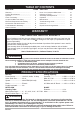
TABLE OF CONTENTS SECTION PAGE SECTION Warranty ............................................... Product Specifications .......................... Symbols ................................................ Power Tool Safety ................................. Compound Miter Saw Safety ................. Electrical Requirements and Safety ...... Accessories and Attachments ............... Tools Needed for Assembly .................. Carton Contents ....................................
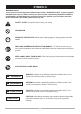
SYMBOLS WARNING ICONS Your power tool and its Operator’s Manual may contain “WARNING ICONS” (a picture symbol intended to alert you to, and/or instruct you how to avoid, a potentially hazardous condition). Understanding and heeding these symbols will help you operate your tool better and safer. Shown below are some of the symbols you may see. SAFETY ALERT: Precautions that involve your safety. PROHIBITION WEAR EYE PROTECTION: Always wear safety goggles or safety glasses with side shields.
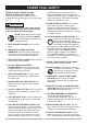
POWER TOOL SAFETY GENERAL SAFETY INSTRUCTIONS BEFORE USING THIS POWER TOOL Safety is a combination of common sense, staying alert and knowing how to use your power tool. ! The table on page 7 shows the correct size to use depending on cord length and nameplate ampere rating. If in doubt, use the next heavier gauge. The smaller the gauge number, the heavier the cord. 11.WEAR PROPER APPAREL. Do not wear loose clothing, gloves, neckties, rings, bracelets or other jewelry which may get caught in moving parts.
POWER TOOL SAFETY to determine that it will operate properly and perform its intended function – check for alignment of moving parts, binding of moving parts, breakage of parts, mounting and any other conditions that may affect its operation. A guard or other part that is damaged should be properly repaired or replaced. 20.NEVER LEAVE THE TOOL RUNNING UNATTENDED. TURN THE POWER “OFF”.
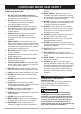
COMPOUND MITER SAW SAFETY stop before returning the saw to the raised position. 20. MAKE SURE the blade has come to a complete stop before removing or securing the workpiece, changing the workpiece angle or changing the angle of the blade. 21. NEVER cut metals or masonry products with this tool. This miter saw is designed for use on wood and wood-like products. 22. NEVER cut small pieces. If the workpiece being cut would cause your hand or fingers to be within 6-3/4 in.
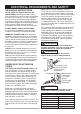
ELECTRICAL REQUIREMENTS AND SAFETY NOTE: When using an extension cord on a circuit with a #14 wire, the extension cord must not exceed 25 feet in length. Before connecting the motor to the power line, make sure the switch is in the off position and the electric current is rated the same as the current stamped on the motor nameplate. Running at a lower voltage will damage the motor. This tool is intended for use on a circuit that has a receptacle like the one illustrated in Fig. 1.
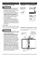
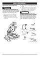
ACCESSORIES AND ATTACHMENTS TOOLS NEEDED FOR ASSEMBLY RECOMMENDED ACCESSORIES SUPPLIED NOT SUPPLIED Blade Wrench Adjustable Wrench Hex Key Combination Square ! WARNING ● Use only accessories recommended for this miter saw. Follow instructions that accompany accessories. Use of improper accessories may cause hazards. ● The use of any cutting tool except 10 in. saw blades which meet the requirements under recommended accessories is prohibited.
CARTON CONTENTS UNPACKING YOUR MITER SAW ! 2. Place the saw on a secure stationary work surface. 3. Separate all parts from the packing material. Check each of the illustrations shown below to make certain all items are accounted for, before discarding any packing material. WARNING To avoid injury from unexpected starting or electrical shock, do not plug the power cord into a source of power during unpacking and assembly. This cord must remain unplugged whenever you are working on the saw.
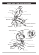
KNOW YOUR COMPOUND MITER SAW Safety Lock-Off Button Upper Plate Guard Cover Plate Motor Dust Bag Lower Blade Guard Hold-down Clamp Base Bevel Scale Positive Stop Locking Lever Hand Hold for Transportation Miter Angle Pointer Miter Lock Handle Switch Handle ON/OFF Trigger Switch Arbor Lock Laser On/Off Switch Laser Guide Fence Hold-down Latch Table Bevel Lock Handle Miter Scale Rear Extension Stay Table Insert Hand Hold for Transportation 10
GLOSSARY OF TERMS COMPOUND MITER SAW TERMS on machine and legible. ARBOR LOCK – Allows the user to keep the blade from rotating while tightening or loosening the arbor bolt during blade replacement or removal. WRENCH STORAGE – Convenient storage to prevent misplacing the blade wrench. BASE – Supports the table, holds accessories and allows for workbench or leg set mounting. ARBOR – The shaft on which a blade is mounted. BEVEL LOCKING HANDLE – Locks the miter saw at a desired bevel angle.
ASSEMBLY AND ADJUSTMENTS INSTALLING THE MITER HANDLE (FIG. A) 1. Thread the miter handle (1) into the hole (2) located at the front of the miter table. INSTALLING THE DUST BAG (FIG. C) 1. Squeeze the metal collar wings (2) of the dust bag (1). 2. Place the dust bag neck opening around the exhaust port (3), and release the metal collar wings. Fig. A Fig. C 2 1 2 1 ! WARNING To avoid injury and damage to the saw, transport or store the miter saw with the cutting head locked in the down position.
Fig. E REMOVING OR INSTALLING THE BLADE 2 ! WARNING Only use a 10-inch diameter blade. To avoid injury from an accidental start, make sure the switch is in the OFF position and plug is not connected to the power source outlet. Removing Blade (Fig. G, H, I) 1. Unplug the saw from the outlet. 2. Allow the cutting head to rise to the upright position. Raise the lower blade guard (1) to the up position. (Fig. G) 3. Loosen the cover plate screw (2) with a Phillips screwdriver. 4.
the table and check for any contact with the metal base or the turn table. NOTE: Pay attention to the pieces removed, noting their position and direction they face. Wipe the blade collars clean of any sawdust before installing the new blade. ADJUSTMENT INSTRUCTIONS ! Fig. I 7 6 8 WARNING To avoid injury from an accidental start, make sure the switch is in the OFF position and the plug is not connected to the power source outlet. 6 ADJUSTING FENCE SQUARENESS (FIG. J) 1.
BEVEL STOP ADJUSTMENT (FIG. M, N, O) and then secure by tightening the miter 5. If the miter angle desired is not one of the nine positive stops, simply lock the miter table into position by turning the miter handle in the clockwise direction. To Adjust the Indicator: (1) Adjust the indicator (3) to the 0 ° mark on the miter scale (4) to position the miter table. (2) Release positive stop locking lever (2). Tighten miter handle.
90° Bevel Indicator (Fig. N) 1. When the blade is exactly 90° to the table, loosen the bevel indicator screw (5) using a #2 Phillips screwdriver. 2. Adjust bevel indicator (6) to the “0” mark (7) on the bevel scale and retighten the screw. MOUNTING THE MITER SAW (FIG. P, Q) ! WARNING To avoid injury from unexpected saw movement: ● Before moving the saw, disconnect the power cord from the outlet, and lock the cutting arm in the lower position using the stop latch.
NOTE: Mounting hardware is not included with this tool. Bolts, nuts, washers, and screws must be purchased separately. ● 2. For portable use, place the saw on a 3/4 in. thick piece of plywood. Bolt the base of the miter saw securely to the plywood using the mounting holes on the base. Use C-clamps to clamp this mounting board to a stable work surface at the worksite. Laser Warning Label: Max output <1mW DIODE LASER: 630-670nm, Complies with 21CFR 1040.10 and 1040. 11. Fig.
OPERATION SAFETY INSTRUCTIONS FOR BASIC SAW OPERATION ● BEFORE USING THE MITER SAW ! WARNING ● To avoid mistakes that could cause serious, permanent injury, do not plug the tool in until the following steps are completed: ● Completely assemble and adjust the saw, following the instructions. (ASSEMBLY AND ADJUSTMENTS) ● Learn the use and function of the ON/OFF switch, lock-off switch, upper and lower blade guards, hold down latch, bevel lock handle and cover plate screws.
● Make sure there are no gaps between the PLAN YOUR WORK ● Use the right tool. Don’t force a tool or attachment to do a job it was not designed to do. Use a different tool for any workpiece that can’t be held in a solidly braced, fixed position. workpiece, fence and table that will let the workpiece shift after it is cut. ● Keep the cut off piece free to move sideways after it is cut off. Otherwise, it could get wedged against the blade and thrown violently. ● Only the workpiece should be on the saw table.
BODY AND HAND POSITION (FIG. S) ! TURNING SAW ON (FIG. T) To reduce the likelihood of accidental starting, a thumb activated lock-OFF switch is located on top of the switch handle. The lock-OFF switch (1) must be pushed in before the trigger switch (2) can be activated and the miter saw started. WARNING Never place hands near the cutting area. Proper positioning of your body and hands when operating the miter saw will make cutting easier and safer. Keep children away.
BEVEL CUT (FIG. V) Fig. X 1. When a bevel cut is required, loosen the bevel lock handle (1). 2. Tilt the cutting head to the desired angle as shown on the bevel scale (2). The blade can be positioned at any angle, from a 90° straight Hold-Down cut (0° on the scale) to a 45° left bevel. Clamp 3. Tighten the bevel lock handle (1) to lock the cutting head in position. 4. Positive stops are provided at 0° and 45°. Workpiece Fig. V CUTTING BASE MOLDING (FIG.
In order to accurately cut crown molding for a 90° inside or outside corner, lay the molding with its broad back surface flat on the saw table. NOTE: The chart below references a compound cut for crown molding ONLY WHEN THE ANGLE BETWEEN THE WALLS EQUALS EXACTLY 90°. When setting the bevel and miter angles for compound miters, remember that the settings are interdependent; changing one changes the other, as well. Fig. Z KEY F e n c e BEVEL MITER TYPE OF CUT SETTING SETTING IL 33.9° IR 33.9° OL 33.
MAINTENANCE MAINTENANCE ! LOWER BLADE GUARD Do not use the saw without the lower blade guard. The lower blade guard is attached to the saw for your protection. Should the lower guard become damaged, do not use the saw until the damaged guard has been replaced. Develop a regular check to make sure the lower guard is working properly. Clean the lower guard of any dust or buildup with a damp cloth. DANGER To avoid injury, never put lubricants on the blade while it is spinning.
TROUBLESHOOTING GUIDE ! WARNING To avoid injury from accidental starting, always turn switch OFF and unplug the tool before moving, replacing the blade or making adjustments. TROUBLESHOOTING GUIDE - MOTOR PROBLEM PROBLEM CAUSE Brake does not 1. Motor brushes not sealed or lightly stop the blade sticking. within 6 seconds. 2. Motor brake overheated from use of defective or wrong size blade or rapid ON/OFF cycling. 3. Arbor bolt loose. 4. Brushes cracked, damaged, etc. 5. Other. Motor does not start 1.
PARTS LIST 10 in. COMPOUND MITER SAW ! MODEL NO. 137.212360 WARNING When servicing use only CRAFTSMAN replacement parts. Use of any other parts many create a HAZARD or cause product damage. Any attempt to repair or replace electrical parts on this Miter Saw may create a HAZARD unless repair is done by a qualified service technician. Repair service is available at your nearest Sears Service Centre. PARTS LIST FOR SAW SCHEMATIC I.D.
10 in. COMPOUND MITER SAW MODEL NO. 137.
10 in. COMPOUND MITER SAW MODEL NO. 137.212360 PARTS LIST AND SCHEMATIC FOR MOTOR I.D. Description I.D. Description X3P0 HEX. SOC. HD. CAP SCREW Size QTY 1 X3QJ LABEL 1 X3PK LABEL 1 X3QK BRUSH ASS’Y 2 X3PL BRUSH HOLDER ASS’Y 2 X3QL 1 X3PM BRUSH COVER 2 X3QM CR. RE. PAN HD. TAPPING SCREW ST5*65 2 X3PQ MOTOR HOUSING 1 X3QN FIELD ASS’Y 1 X3PR BEARING 1 X3QU HEX. SOC. HD. CAP SCREW X3PS SPRING 1 X3QR HEX. SOC. HD.
REPAIR PROTECTION AGREEMENTS Congratulations on making a smart purchase. Your new Craftsman® product is designed and manufactured for years of dependable operation. But like all products, it may require repair from time to time. That’s when having a Repair Protection Agreement can save you money and aggravation.
Get it fixed, at your home or ours! Your Home For expert troubleshooting and home solutions advice: www.managemyhome.com For repair – in your home – of all major brand appliances, lawn and garden equipment, or heating and cooling systems, no matter who made it, no matter who sold it! For the replacement parts, accessories and owner’s manuals that you need to do-it-yourself. For Sears professional installation of home appliances and items like garage door openers and water heaters.