
Specifications


AC Drives and Delta-Wave Motors
9
4
motor control through zero speed. The frequency range can
be varied from 3 to 400 Hz with constant torque available up
to 60 Hz, and constant horsepower available above 60 Hz.
The drive features solid-state reversing with adjustable accel-
eration and deceleration. They also feature adjustable current
limit and I
2
T class 10 current trip to protect the motor, thermal
protection, line starting and stopping, min. and max. speed
control, slip compensation, acceleration torque boosting con-
trol, and many more features. Standard models are available
to power induction motors up to 1 Hp.
The key advantages of this motor design vs. the permanent
magnet brush or permanent magnet BLDC motor line is sim-
plicity, reliability, and durability. Positional feedback and high
energy rare earth magnets are not necessary with this type of
machine. Users may take advantage of standard power lines
and wall outlets offering 115 VAC or 230 VAC. The com-
plexity of these past machines did not come from the motor,
but the control of that motor. Minarik has developed the ideal
economical drive solution to this dilemma with the aforemen-
tioned MAC drive. This drive gives you complete control of
our Delta-Wave motors as well as any three phase induction
motor.
Minarik's system solution approach is ideal for applications
involving web handling, conveyors, fans, blowers, pumps,
compressors, stirring machines, etc. Contact a Minarik rep-
resentative to find out more about our AC solutions for your
application.
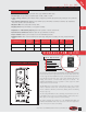
inarik now offers 3-phase induction motors that
are wound for either 230 VAC or 115 VAC
input. Our Delta-Wave (AC) induction motors use
three phases of alternating current supplied to the sta-
tor to provide the speed and torque necessary for your
motion control needs. These currents rise and fall in
polarity much like an ocean wave. The waves circu-
late around the stator core at a frequency determined
by the user and a drive such as our variable frequency
MAC drive. The rotor of the AC motor consists of mul-
tiple current paths (coils) integrated throughout an iron
core. This rotor construction is typically known as a
squirrel cage design. Reaction between stator and
rotor coils result by transformer action across the sta-
tor/rotor air gap. The induction motor is essentially a
transformer with a rotating secondary. The force that
exists between primary and secondary coils in a trans-
former appears as useful torque in an induction motor.
The rotor is pushed into rotation by the ensuing stator
wave. The frequency of the waves establishes the max-
imum speed but it does not provide the torque neces-
sary to run at that speed. The voltage and resulting
current provide the actual power to do the work.
RPM = (120 x Hz)/Poles
The stator field rotates at a speed determined by the
frequency and number of poles. The rotor always turns
at a lower speed than the stator fields; if the rotor
turned at a synchronous speed, there would be no
change in flux linkage, no induced current, and no
torque. The small difference in speed that produces
flux cutting and motor action is called the slip.
By definition percent slip is:
s = (N
stator
- N
slip
) /N
stator
) x 100
The output shaft speed is :
N
rotor
= N
sync
- (N
sync
x5
)
Our MAC drive accepts either 115 VAC or 230 VAC
input and provides respective 3 phase PWM output for
these induction motors. The PWM output gives us a
high dynamic response for high performance use, a
very wide speed range (up to 100:1), and smooth
M
AC Solutions
Call us toll free 1•800•MINARIK or download manuals at www.minarikdrives.com
F
AC DRIVES & MOTORS