
Specifications


Isolation
otor windings are simply coils of wire separated by
insulating material. Only the base and outside of the
motor is touching “earth ground.” The drives use one of the
wires coming from these motor coils as “common”. Common
is the point in the control circuit from which all other internal
voltages are referenced. This part of the motor coil is the
drive’s zero reference.
Common and earth ground are at a high voltage potential
from each other, typically equal to the line voltage. If we
plugged a drive into a 115 VAC line socket, and measured the
voltage from the drive’s common to earth ground, we would
see about 115 VAC. We say the drive floats above ground
since these two points have a very large potential difference.
Often control signals from an external source (such as a PLC or
transducer) are referenced to earth ground. If we set a ground-
ed 0-10V analog signal to 0V, and measure from that point to
earth ground, we would see “0V”. An attempt to connect
this source directly into the drive would result in cata-
strophic failure of the signal source and/or the drive.
Therefore, we must use a device that provides good elec-
trical isolation between these two points. An isolation
device takes the incoming voltage from the signal source,
and makes an “image” of this voltage, but isolated, for the
drive to use as the reference. The output voltage is isolat-
ed from the ground and safe to wire to the drive.
There are three basic methods of isolation used by
Minarik:
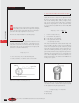
This is the simplest and least linear method of isolation
because an opto-coupler is designed to be an on-off
device, not a variable voltage device. As a result, we
occasionally receive voltage drops across certain junc-
tions, and non-linearity due to temperature and age.
However, this method is still acceptable for some appli-
cations. We use opto-coupled isolation in some older
Minarik products like the PCM3 and the CF20000 dri-
ves.
Minarik uses a simple push-pull transistor pair to trans-
form an external DC signal into square-wave AC. SInce
transformers can only transmit AC, the DC signal from the
remote source must be “sampled” into AC. Then, the sig-
nal goes through a 1:1 isolation transformer; subsequent-
ly, a bridge rectifier converts it back into DC. This method
is 2 to 3 times more linear than an opto-coupled device,
but voltage drops still exist across the transistors and diode
bridge. Our PCM20000, MM-PCM and PCMXP drives
use this method.
This is Minarik’s most reliable method of isolation. The
Integrated Circuit (IC) uses a uniquely isolated op- amp,
with feedback for excellent linearity. It is 300 times more
linear than the opto-coupler and has better isolation than
the other devices. More complex, the Burr-Brown IC
requires support circuitry to run. Minarik provides separate
isolation modules to use with any motor drive, or with iso-
lation directly integrated into a drive. Minarik’s PCM4 iso-
lation module, PCM adder card, RG5500U, MM300,
MM-PCM and MM500 series of drives use this method.
1. Opto-Coupled Isolation
2. Isolation Transformers
3. Burr-Brown’s® ISO Chip
M
0 61
Call us toll free 1•800•MINARIK or download manuals at www.minarikdrives.com
K
REFERENCE