
Operating instructions


PTQ-MCM ♦ Quantum / Unity Platform Reference
Modbus Communication Module
Page 102 of 139 ProSoft Technology, Inc.
April 29, 2008
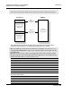
Note: Command Control blocks are not copied to the module database. You must define variables
in the module's main memory, and use processor logic to process the command control request.
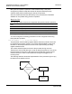
Step 2
Process Command
Control Request
Processor
Module
Step 1
Command Control
Request
Step 3
Command Control
Response
Words 1 to 64
Command Control
Words 1 to 64
Command Control
Words 65 to 164
Holding Register
(Write area)
Words 65 to 164
Input Register
(Read area)
The following table shows the contents of the command control area when a
command control block such as 9998 (Warm Boot module) is issued.
Note: The diagram above shows the memory addresses for a Quantum / Unity processor. If you
are deploying the PTQ-MCM with a Unity processor, substitute %MW for read only data, and %IW
for read/write data.
Note: The processor memory locations in the example tables below use the 3x register start and
4x register start values defined in Backplane Data Transfer (page 99). You can configure any valid
3x and 4x start address that is not used by other processes.
Command Control Word Description
40001 Output sequence number
40002 Block ID
40003 Block request word 1
40004 Block request word 2
40005 Block request word 3
… …
40064 Block request word 62
The following table shows the results of the PTQ-MCM response to the
command control block.
Command Control Word Description
30001 Input sequence number
30002 Block ID
30003 Block response word 1