
User manual


ILX34-AENWG ♦ Point I/O Platform Ladder Logic
Wireless POINT I/O Adapter User Manual
ProSoftTechnology,Inc. Page131of209
September19,2011
5 Ladder Logic
In This Chapter
AdjustingtheInputandOutputArraySizes(Optional)...................................131
1734POINTI/OModule/RSLogix5000ControllerTagReference...................133
5.1 Adjusting the Input and Output Array Sizes (Optional)
Themoduleinternaldatabaseisdividedintotwouser‐configurableareas:
ReadData
WriteData.
TheReadDataareaismovedfromthemoduletotheprocessor,whiletheWriteDataareais
movedfromtheprocessortothemodule.Youcanconfigurethestartregisterandsizeof
each
area.ThesizeofeachareayouconfiguremustmatchtheAdd‐Oninstructioncontrollertagarray
sizesfortheR
EADDATAandWRITEDATAarrays.
TheILX34‐AENWGsampleprogramisconfiguredfor600registersofR
EADDATAand600registers
ofW
RITEDATA,whichissufficientformostapplication.Thistopicdescribeshowtoconfigureuser
dataforapplicationsrequiringmorethan600registersofReadDataandWriteData.
Important: Because the module pages data in blocks of 200 registers at a time, you must
configure your user data in multiples of 200 registers.
Caution: When you change the array size, RSLogix may reset the AENWG tag values to zero. To
avoid data loss, be sure to save your settings before continuing.
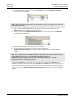
1 IntheCONTROLLERORGANIZATIONwindow,expandtheDATATYPESandUSER‐DEFINEDfolders,
andthendouble‐clickAENWGDATA.
ThisactionopensaneditwindowfortheAENWGDATA
datatype.