
Instructions / Assembly

Page 15 of 25
¾ Cut a square hole and clear any roofing material so that a proper frame can be installed.
¾ When cutting the opening, allowance must be made for the thickness of the frame.
In the event that roof joists must be cut - follow the building codes having jurisdiction for reframing the opening.
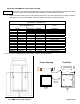
¾ For roof curb installations (recommended): Refer to the Curb Size in the Framing Chart for box framing sizes for masonry
pour. Roof curbs may also be purchased at your local building supply store.
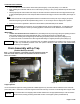
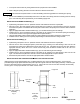
INSTALLING ON A FRAMED OPENING (Fig. 1)
¾ Implementing “best practice” and / or “preferred” methods. Drill sufficient holes in the roof jack plate.
¾ Place the Z-vent Roof Jack Support System (conical side up) by centering it over and lowering it down onto the frame
and transfer the position of the drilled holes from the plate onto the frame. Temporarily remove the Roof Jack for adhesive
application.
¾ Apply the appropriate weather resistant adhesive (Fig. 1) to the frame observing the hole markings.
¾ Install the Z-vent Roof Jack Support System (conical side up) by centering it over the framed opening and lowering it
onto the frame and secure it using screws equipped with neoprene washers.
¾ Using the appropriate roofing methods reapply the roofing material over the plate to maintain the roofing integrity.
¾ Install the Z-Vent flashing over the roof jack by implementing the standard contractor roofing methods.
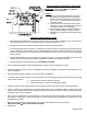
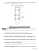
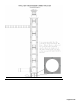
INSTALLING ON A CURB (Fig. 2)
¾ Implementing “best practice” and / or “preferred” methods. Drill sufficient holes in the roof jack plate.
¾ Place the Z-vent Roof Jack Support System (conical side up) by centering it over and lowering it down onto the curb
and transfer the location of the drilled holes from the plate onto the curb. Temporarily remove the Roof Jack. Select the
appropriate masonry drill bit size for the concrete screws being used and drill the marked holes in the curb to the
prescribed depth.
¾ Apply the appropriate weather resistant adhesive (Fig. 2) to the curb observing the hole markings.
¾ Install the Z-vent Roof Jack Support System (conical side up) by centering it over and lowering it down onto the curb
again. This time fasten the plate to the curb with concrete screws equipped with neoprene washers.
¾ Seal where the plate meets the curb with the appropriate weather resistant sealant.
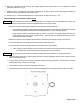
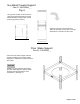
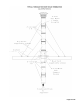
INSTALLING VENT PIPE THROUGH Z-VENT ROOF JACK SUPPORT SYSTEM
Utilizing the Roof Jack Coupling assembly (Fig. 3) supplied with the Z-vent Roof Jack Support System. Connect the two
prescribed lengths of pipe (above and below roof) and couple them together with Roof Jack Coupling Assembly. Position the pipe
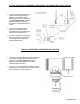
joint in the notched area of the coupling assembly (see Fig. 4). Tighten the lock-nuts onto the bolts that clamp the assembly
onto the pipe to a torque specification of 70 in/lbs / 6 ft-lbs / 8 Nm.
NOTICE
Roof Jack Coupling
Assembly
Fig. 3
Pipe Joint
Range
Roof Jack
Pipe
Assembly
Fig. 4
Outside
UP
DOWN
Inside
Pipe
Joint
Small end
Large end