
Instructions / Assembly

Page 10 of 25
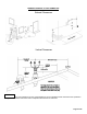
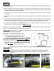
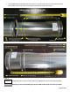
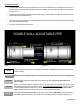
Double Wall Adjustable:
¾ The Double Wall Adjustable Pipe adds approximately 9 inches to the overall length PLUS the adjustment range up to a
maximum range of 6-1/2 inches for pipe diameters 3in thru 12in OR 5-1/2 inches for pipe diameters 14in thru 24in (see
images 13 & 14).
¾ Following the double wall pipe connection instructions above (pg. 6) make certain that the pipes are inserted to the full
insertion depth for the required diameter.
¾ Once the proper length is achieved with the adjustable pipe, the adjustment sleeve can slide to close the outer wall until
the inner bead clicks with the locks.
¾ Secure the gear clamp to lock slider in place.
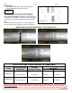
Image 13 Image 14
Installer shall mark the minimum insertion depth on the double wall adjustable pipe small end and insert to at
least this marking.
Neglecting to insert adjustable pipe to the prescribed insertion depth may result in joint integrity failure.
Adjustable pipes should not be inserted into a tee, elbow or any other fitting past the prescribed 2 inch
insertion depth.
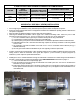
Where a non-standard length is required between 9”-15” adjustable range the inner pipe of the Double
Wall Adjustable Pipe may be cut. Refer to section “
TO CUT PIPE FOR SINGLE WALL ONLY” on page 8. Once the
cut is completed engage inner wall into a tee, elbow or any other fitting to the prescribed 2 inch insertion
depth and slide the outer wall closed to engage the snap lock and tighten gear clamp.
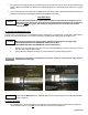
Inserting the adjustable pipe TOO FAR into a tee, elbow or any other fitting BEYOND the prescribed insertion
depth WILL constrict the vent size in the tee, elbow or any other fitting thereby choking the exhaust gases.
NOTICE
WARNING!
CAUTION!
WARNING!
CAUTION!