
11.0
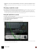
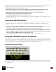

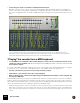
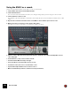
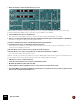
Table Of Contents
- Table of Contents
- Introduction
- Overview
- Audio and MIDI Basics
- Using Reason Rack Plugin as an Instrument
- Using Reason Rack Plugin as an Effect
- Working in the Rack
- Routing Audio and CV
- Sounds, Patches and the Browser
- The I/O device
- Kong Drum Designer
- Introduction
- Overview
- About file formats
- Using patches
- Pad Settings
- The Drum and FX section
- The Drum modules
- The Support Generator modules
- The FX modules
- Connections
- Using Kong as an effect device
- Using external effects with Kong
- Redrum Drum Computer
- Introduction
- About file formats
- Using patches
- Programming patterns
- Redrum parameters
- Using Redrum as a sound module
- Connections
- Dr. Octo Rex Loop Player
- Introduction
- About REX file formats
- Loading and saving Dr. Octo Rex patches
- Playing Loops
- Adding Loops
- Playing individual Loop Slices
- Slice handling
- Dr. Octo Rex panel parameters
- Dr. Octo Rex synth parameters
- Connections
- Europa Shapeshifting Synthesizer
- Introduction
- Panel overview
- Signal flow
- Playing and using Europa
- Panel reference
- Sound Engines On/Off and Edit Focus section
- The Oscillator section
- The Modifiers section
- The Spectral Filter
- The Harmonics section
- The Unison section
- The User Wave and Mixer section
- The Filter section
- The Amplifier section
- The Envelopes section
- Envelope 1, 2, 3 and 4
- Preset
- Adding a Sustain stage
- Adding and removing envelope points
- Changing the envelope curve shape
- Looping the envelope
- Editing levels only
- Creating “free form” envelope curves
- Using the Envelope 3 and Envelope 4 curves as Sound Engine waveforms
- Using the Envelope 4 curve as a Spectral Filter curve
- The LFO section
- The Effects section
- The Modulation Bus section
- Connections
- Tips and Tricks
- Grain Sample Manipulator
- Thor Polysonic Synthesizer
- Subtractor Synthesizer
- Malström Synthesizer
- Monotone Bass Synthesizer
- ID8 Instrument Device
- Rytmik Drum Machine
- Radical Piano
- Klang Tuned Percussion
- Pangea World Instruments
- Humana Vocal Ensemble
- NN-XT Sampler
- Introduction
- Panel overview
- Loading complete Patches and REX files
- Using the main panel
- Overview of the Remote Editor panel
- About Samples and Zones
- Selections and Edit Focus
- Adjusting parameters
- Managing Zones and Samples
- Working with Grouping
- Working with Key Ranges
- Setting Root Notes and Tuning
- Using Automap
- Layered, crossfaded and velocity switched sounds
- Using Alternate
- Sample parameters
- Group parameters
- Synth parameters
- Connections
- NN-19 Sampler
- Introduction
- General sampling principles
- About audio file formats
- About Key Zones and samples
- Loading a Sample into an empty NN-19
- Loading SoundFont samples
- Loading REX slices as samples
- Creating Key Zones
- Selecting Key Zones
- Setting the Key Zone Range
- Deleting a Key Zone
- About Key zones, assigned and unassigned samples
- Adding sample(s) to a Key Map
- Setting the Root Key
- Removing sample(s) from a Key Map
- Removing all unassigned samples
- Rearranging samples in a Key Map
- Setting Sample Level
- Tuning samples
- Looping Samples
- About the Solo Sample function
- Automap Samples
- NN-19 synth parameters
- Play Parameters
- Connections
- Quartet Chorus Ensemble
- Sweeper Modulation Effect
- Alligator Triple Filtered Gate
- Pulveriser
- The Echo
- Scream 4 Sound Destruction Unit
- BV512 Vocoder
- Introduction
- Setting up for vocoding
- Using the BV512 as an equalizer
- BV512 parameters
- Connections
- Tips and tricks
- RV7000 Mk II Advanced Reverb
- Neptune Pitch Adjuster and Voice Synth
- Introduction
- Overview and basic concepts
- Setting up for pitch processing
- Using pitch correction
- Using pitch shifting (Transpose)
- Using Formant control
- Using the Voice Synth
- Panel parameters
- Connections
- Softube Amps
- Audiomatic Retro Transformer
- Channel Dynamics Compressor & Gate
- Channel EQ Equalizer
- Master Bus Compressor
- Synchronous Timed Effect Modulator
- The MClass Effects
- Half-Rack Effects
- The Combinator
- Pulsar Dual LFO
- RPG-8 Arpeggiator
- Matrix Pattern Sequencer
- Mixer 14:2
- The Line Mixer 6:2
- Working with Players
- Settings
- The Reason Rack Plugin Settings dialog
- Index

BV512 VOCODER576
This is essentially the required connections, but for best results it’s a good idea to add some distortion and/or com-
pression to the carrier signal - this increases the amount of high frequencies in the carrier signal:
5. Press [Shift] and create a Scream 4 distortion device.
6. Connect the distortion device as an insert effect between the Spider and the carrier input of the vocoder.
Now, the carrier signal will be processed in the distortion device, but not the modulator signal.
7. Play back the pattern and experiment with the settings on the vocoder and distortion device.
D This technique can also be used to process vocals and speech.
D Try adjusting the Shift parameter for new effects and sounds.
Remember that you can route CV to the Shift parameter on the back of the BV512 - use e.g. a Matrix or an LFO
output on a synth device!
Controlling the Hold function
As described in “Hold button”, pressing the Hold button on the front panel “freezes” the current filter spectrum until
you deactivate it again. This can be used for creating sample & hold-like effects, stuttering or garbled vocoder
sounds:
D Connect e.g. the Gate output on a Matrix device to the Hold input on the back of the BV512.
By playing back a gate pattern on the Matrix, the Hold function will repeatedly be turned on and off according to
the programmed rhythm in the pattern. Hold will be active for the length of each gate signal.
D Automate the Hold function with the main sequencer, either by recording it or by drawing in its controller lane.
• If you route MIDI to the BV512 you can control the Hold function in two ways by default: By pressing a damper
pedal connected to your MIDI controller or by playing the note C4.
In both cases, the Hold function will be momentary - Hold is on until you release the pedal or key.
Using the individual band level connections
As described in “Individual band levels”, the individual band level connectors on the back are CV output and input
jacks. The upper row sends out the CV signals from the envelope followers for the different frequency bands, while
the lower jacks are CV inputs for controlling the individual bandpass filters (breaking the internal connection from the
envelope followers). There are several interesting things you can do with these connections:
Crosspatching frequency bands
By connecting outputs to inputs in alternative configurations, you can drastically change the result of the vocoding.
For example, you could have low frequencies in the modulator signal give high frequencies in the vocoded sound and
vice versa. Note: