
12.25


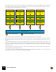
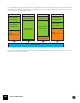


Table Of Contents
- Table of Contents
- Introduction
- Common Operations and Concepts
- On-screen Piano Keys
- Audio Basics
- Sequencer Functions
- About this chapter
- Introduction
- Sequencer area overview
- Track details
- Track definition
- The relationship between the track, the rack and the Main Mixer
- Master Keyboard Input
- The relationship between tracks, lanes, clips and events
- Track types
- Track List elements
- Creating tracks
- Selecting tracks
- Resizing tracks
- Moving tracks
- Deleting tracks
- Duplicating/copying tracks and devices
- Coloring tracks
- Naming tracks
- Folding tracks
- Muting tracks
- Soloing tracks
- Lane details
- Clip basics
- Toolbar details
- Ruler details
- Transport Panel details
- Keys
- Groove
- Q Record
- Quantize value
- Quantize
- Sync Mode
- Song Position
- About subticks in the Song Position display
- Time Position
- Click On/Off
- Pre(-count) On/Off
- Click Level
- Tempo
- Tap Tempo
- Signature
- Rewind and Fast Forward
- Play and Stop
- Record
- Dub and Alt
- Loop On/Off
- Go to Left and Right Locators
- Left and Right Locator Positions
- Transport keyboard commands
- About the Inspector
- Recording in the Sequencer
- About this chapter
- General recording functions
- Audio recording details
- Note recording details
- Parameter automation recording details
- Performance controllers vs. track parameter automation
- Recording performance controller automation
- Recording parameter automation into Note Clips
- Recording performance controller automation over or into an existing clip
- About performance controller automation on multiple lanes
- Recording parameter automation
- Recording parameter automation in Loop mode
- Recording parameter automation over or into an existing clip
- Adjusting automated parameters during playback - “Live mode”
- Recording parameter automation on multiple tracks
- Pattern automation recording details
- Tempo automation recording
- Arranging in the Sequencer
- About this chapter
- Clip handling
- Creating Clips
- Selecting clips
- Setting audio clip Level and Fades
- Deleting clips
- Resizing (masking) clips
- About masked recordings and events
- Tempo scaling clips
- Moving clips
- About overlapping clips
- Duplicating clips
- Cutting, Copying and Pasting clips
- Naming clips
- Coloring clips
- Splitting clips
- Crossfading audio clips
- Joining clips
- Reversing clips
- Muting clips
- Merging clips on note lanes
- Bounce in Place
- Matching clips using the “Match Values” function
- Inserting bars
- Removing bars
- Audio Editing in the Sequencer
- About this chapter
- Edit Modes, Stretch & Transpose Types and Clip Types
- Editing audio in Slice Edit mode
- Editing audio in Pitch Edit mode
- Pitch Editor elements
- Selecting notes
- Auditioning notes
- Correcting pitches
- Changing transposition
- Resetting pitches
- Splitting the clip at notes
- Reverting all notes
- Attenuating pitch drift/vibrato
- Editing transition times
- Moving notes and changing note lengths
- Quantizing notes
- Splitting and joining notes
- About switching from Pitch Edit mode to Slice Edit mode
- Audio pitch editing in the Inspector
- Editing audio in the Comp Editor
- Audio clip elements in the Comp Editor
- The relationship between Clips, Comp Rows and Recordings
- Comp Editor window handling
- Comp Editor audio editing tools
- Selecting a Comp Row for playback in a Single Take clip
- Selecting Comp Rows
- Deleting Comp Rows
- Moving Comp Rows
- Duplicating Comp Rows
- Cutting, copying and pasting Comp Rows
- Adjusting the Comp Row Level
- Adjusting the Recording Offset
- Comping audio
- Common audio editing functions
- Changing the tempo and transposition of the audio
- Audio and tempo matching
- Editing audio using the Inspector
- Note and Automation Editing
- About this chapter
- The Edit Mode
- Tool Window editing tools
- Note editing
- Selecting notes
- Drawing notes
- Deleting notes
- Resizing notes
- Muting notes
- Splitting notes
- Moving notes
- Moving notes manually
- About moving notes outside or between clips
- Changing note pitches (transpose) with the arrow keys
- Nudging note positions with the arrow keys
- About nudging notes outside an open clip
- Moving notes with the “Alter Notes” function
- Moving notes with the “Extract Notes to Lanes” and “Explode” functions
- Moving notes in the Inspector
- Duplicating notes
- Using Cut, Copy and Paste
- Quantize
- Pitch (Transpose)
- Extract Notes to Lanes
- Scale Tempo
- Editing note velocity
- Reverse
- Multi Lanes editing
- Automation editing
- Overview
- Editing parameter automation
- Drawing parameter automation events
- Creating curves between automation points
- Deleting automation events
- Reversing automation events
- Editing performance controller automation
- About Automation Cleanup
- Editing pattern automation
- Drawing pattern automation
- Moving, resizing and duplicating pattern automation clips
- Deleting pattern automation clips
- The “Convert Pattern Automation to Notes” function
- Editing tempo automation
- About tempo changes and tempo automation of audio tracks
- Automating time signature
- Moving, resizing and duplicating time signature automation clips
- Deleting time signature automation clips
- Note and automation editing in the Inspector
- Working with Blocks in the Sequencer
- About this chapter
- Introduction
- Arrangement Views
- Editing Blocks in the Block View
- Arranging Blocks in the Song View
- Working with the Rack
- About this chapter
- Rack device procedures
- Navigating in the rack
- Resizing and detaching the rack
- About Device Groups
- Creating devices
- Selecting devices
- Deleting devices
- Re-ordering devices
- Re-routing devices
- Creating new rack columns
- About the “Sort Selected Device Groups” function
- Replacing devices
- Duplicating devices
- Cut, Copy and Paste devices
- Naming devices
- Folding and unfolding devices
- Working with Players
- Working with Rack Extensions
- Working with VST Plugins
- About this chapter
- About VST plugins
- Installing and enabling VST plugins
- Using VST plugins in Reason
- The Plugin Rack Device
- Front panel
- Rear panel
- About auto-routing of VSTs in the rack
- The Plugin Window
- Editing the VST parameters
- Automating VST parameters
- CV modulation of VST parameters
- Remote controlling VST parameters
- Selecting VST programs
- About saving songs that contain VSTs
- Combining VST plugins in Combinator devices
- About missing VST plugins
- Managing VST plugins
- Sounds, Patches and the Browser
- About this chapter
- About patches
- About ReFills
- Using the Browser
- Opening the browser
- Browser elements
- Navigating in the Browser
- Using Locations and Favorites
- Favorites Lists
- Selecting and auditioning samples and REX loops
- Selecting multiple files
- Cross-browsing patch files
- Create Instrument/Create Effect
- About patch formats and sampler devices
- Using the “Search” function
- Loading files
- About browse lists
- Handling Missing Sounds
- Reason file formats
- Routing Audio and CV
- About this chapter
- Signal types
- About cables
- Automatic routing
- Manual routing
- Using CV and Gate
- The Main Mixer
- About this chapter
- Overview
- Navigating in the Main Mixer
- Managing mixer channels
- The channel strip
- The Master Section strip
- Automating mixer parameters
- Working with effects
- Output Busses
- Parallel Channels
- Solo, Mute and Send FX logic
- Remote controlling the Main Mixer
- Advanced routing tips and tricks
- Delay Compensation
- About this chapter
- About Delay Compensation in Reason
- How the Delay Compensation works
- Delay Compensation in individual mixer channels
- Delay Compensation with Busses and Parallel Channels
- Delay Compensation to Send FX busses
- About the Master Insert FX
- Problematic configurations
- About using the Direct Out connections of the mixer channels
- About the Metronome Click
- Recording with Delay Compensation
- Playing and monitoring with Delay Compensation
- About bouncing mixer channels
- Song File Handling
- Importing and Exporting Audio
- Sampling
- The ReGroove Mixer
- Remote - Playing and Controlling Devices
- About the various MIDI inputs
- About Remote
- Setting up
- Remote basics
- Locking a surface to a device
- Remote Override
- Additional Remote Overrides...
- Keyboard Control
- Saving Remote Setups
- Synchronization and Advanced MIDI
- About this chapter
- Synchronization to MIDI Clock
- Synchronization using Ableton Link
- Advanced MIDI - The External Control Bus inputs
- Optimizing Performance
- Introduction
- Optimization and latency reduction
- Optimizing your computer system
- Optimizing Songs
- Global
- Main Mixer
- Sample Players – NN19, NNXT, Dr. Octo Rex, Grain and Redrum
- Filters – Subtractor, Thor, Malström, NN19, NNXT, Grain, Europa and Dr. Octo Rex
- Polyphonic Devices – Subtractor, Thor, Malström, NN19, NNXT, Grain, Europa, Dr. Octo Rex and Redrum
- Subtractor
- Thor
- Malström
- Redrum
- Mixer devices
- Distortion
- Reverb
- Send Effects
- RAM requirements
- Hardware Interface
- Kong Drum Designer
- Introduction
- Overview
- About file formats
- Using patches
- Pad Settings
- The Drum and FX section
- The Drum modules
- The Support Generator modules
- The FX modules
- Connections
- Using Kong as an effect device
- Using external effects with Kong
- Redrum Drum Computer
- Introduction
- Sampling in Redrum
- About file formats
- Using patches
- Programming patterns
- Redrum parameters
- Using Redrum as a sound module
- Connections
- Dr. Octo Rex Loop Player
- Introduction
- About REX file formats
- Loading and saving Dr. Octo Rex patches
- Playing Loops
- Adding Loops
- Playing individual Loop Slices
- Creating sequencer notes
- Slice handling
- Dr. Octo Rex panel parameters
- Dr. Octo Rex synth parameters
- Connections
- Europa Shapeshifting Synthesizer
- Introduction
- Panel overview
- Signal flow
- Playing and using Europa
- Panel reference
- Sound Engines On/Off and Edit Focus section
- The Oscillator section
- The Modifiers section
- The Spectral Filter
- The Harmonics section
- The Unison section
- The User Wave and Mixer section
- The Filter section
- The Amplifier section
- The Envelopes section
- Envelope 1, 2, 3 and 4
- Preset
- Adding a Sustain stage
- Adding and removing envelope points
- Changing the envelope curve shape
- Looping the envelope
- Editing levels only
- Creating “free form” envelope curves
- Using the Envelope 3 and Envelope 4 curves as Sound Engine waveforms
- Using the Envelope 4 curve as a Spectral Filter curve
- The LFO section
- The Effects section
- The Modulation Bus section
- Connections
- Tips and Tricks
- Grain Sample Manipulator
- Mimic Creative Sampler
- Introduction
- Panel overview
- Signal flow
- Playing and using Mimic
- Panel reference
- Connections
- Tips and Tricks
- Thor Polysonic Synthesizer
- Subtractor Synthesizer
- Malström Synthesizer
- Monotone Bass Synthesizer
- ID8 Instrument Device
- Rytmik Drum Machine
- Radical Piano
- Klang Tuned Percussion
- Pangea World Instruments
- Humana Vocal Ensemble
- NN-XT Sampler
- Introduction
- Sampling in NN-XT
- Panel overview
- Loading complete Patches and REX files
- Using the main panel
- Overview of the Remote Editor panel
- About Samples and Zones
- Selections and Edit Focus
- Adjusting parameters
- Managing Zones and Samples
- Working with Grouping
- Working with Key Ranges
- Setting Root Notes and Tuning
- Using Automap
- Layered, crossfaded and velocity switched sounds
- Using Alternate
- Sample parameters
- Group parameters
- Synth parameters
- Connections
- NN-19 Sampler
- Introduction
- General sampling principles
- About audio file formats
- Sampling in NN-19
- About Key Zones and samples
- Loading a Sample into an empty NN-19
- Loading SoundFont samples
- Loading REX slices as samples
- Creating Key Zones
- Selecting Key Zones
- Setting the Key Zone Range
- Deleting a Key Zone
- About Key zones, assigned and unassigned samples
- Adding sample(s) to a Key Map
- Setting the Root Key
- Removing sample(s) from a Key Map
- Removing all unassigned samples
- Rearranging samples in a Key Map
- Setting Sample Level
- Tuning samples
- Looping Samples
- About the Solo Sample function
- Automap Samples
- NN-19 synth parameters
- Play Parameters
- Connections
- MIDI Out Device
- Quartet Chorus Ensemble
- Sweeper Modulation Effect
- Alligator Triple Filtered Gate
- Pulveriser
- The Echo
- Scream 4 Sound Destruction Unit
- BV512 Vocoder
- Introduction
- Setting up for basic vocoding
- Using the BV512 as an equalizer
- BV512 parameters
- Connections
- Automation
- Tips and tricks
- RV7000 Mk II Advanced Reverb
- Neptune Pitch Adjuster and Voice Synth
- Introduction
- Overview and basic concepts
- Setting up for pitch processing
- Using pitch correction
- Using pitch shifting (Transpose)
- Using Formant control
- Using the Voice Synth
- Panel parameters
- Connections
- Pitch adjustment tips and tricks
- Softube Amps
- Audiomatic Retro Transformer
- Channel Dynamics Compressor & Gate
- Channel EQ Equalizer
- Master Bus Compressor
- Synchronous Timed Effect Modulator
- The MClass Effects
- Half-Rack Effects
- The Combinator
- Introduction
- Combinator overview
- Creating a Combinator device
- About internal and external audio connections
- Adding devices to a Combi
- Combinator handling
- Sequencer tracks and playing Combis
- Configuring the Combinator panel
- Assigning panel controls to parameters in the Editor
- Using Modulation Routing
- CV Connections
- Pulsar Dual LFO
- RPG-8 Arpeggiator
- Matrix Pattern Sequencer
- Mixer 14:2
- The Line Mixer 6:2
- Menu and Dialog Reference
- Reason menu (macOS)
- File menu
- New
- New from Template
- Open...
- Open Demo Song
- Close
- Save
- Save As...
- Save and Optimize
- Song Information...
- Song Self-contain Settings...
- Import Audio File...
- Import MIDI File...
- Export MIDI File...
- Export Insert FX Patch...
- Save Device Patch As...
- Export Song/Loop as Audio File...
- Bounce Mixer Channels...
- Export REX as MIDI File...
- Export Device Remote Info...
- Recent Songs list
- Exit (Windows)
- Edit menu
- Undo
- Redo
- Cut/Cut Tracks and Devices/Cut Channels and Tracks
- Copy/Copy Tracks and Devices/Copy Channels and Tracks/Copy Patch
- Paste/Paste Tracks and Devices/Paste Channels and Tracks/Paste Patch
- Delete/Delete Tracks and Devices/Delete Channels and Tracks
- Delete Tracks
- Duplicate Tracks and Devices/Duplicate Channels and Tracks
- Select All/Select All Devices/Select All Tracks/Select All Channels
- Select All in Device Group
- Sort Selected Device Groups
- Auto-route Device
- Disconnect Device
- Combine/Uncombine
- Copy/Paste Channel Settings (Main Mixer channel strips)
- Route to (Main Mixer channel strips)
- Create Parallel Channel (Main Mixer channel strips)
- Clear Insert FX
- Reset All Channel Settings (Main Mixer channel strips)
- Reset Device
- Cut Pattern
- Copy Pattern
- Paste Pattern
- Clear Pattern
- Browse Patches...
- Browse Loops...
- Browse Samples...
- Automap Samples
- Delete Sample/Remove Sample
- Delete Unused Samples
- Split Key Zone
- Delete Key Zone
- Reload Samples
- Add Zone
- Copy Zones
- Paste Zones
- Duplicate Zones
- Delete Zones
- Select All Zones
- Copy Parameters to Selected Zones
- Sort Zones by Note
- Sort Zones by Velocity
- Group Selected Zones
- Set Root Notes from Pitch Detection
- Automap Zones
- Automap Zones Chromatically
- Create Velocity Crossfades
- Copy Loop to Track
- Copy Pattern to Track
- Shift Pattern Left/Right
- Shift Drum Left/Right
- Shift Pattern Up/Down
- Random Sequencer Pattern
- Randomize Pattern
- Randomize Drum
- Alter Pattern
- Alter Drum
- Invert Pattern
- Arpeggio Notes to Track
- Create Track for.../Delete Track for...
- Go To Track for
- Insert Bars Between Locators
- Remove Bars Between Locators
- Edit
- Bounce in Place
- Bounce Clips to New Samples (Audio Clips)
- Bounce Clip to Disk... (Audio Clips)
- Bounce Clips to New Recordings (Audio Clips)
- Bounce Clip to REX Loop (Single Take Audio Clips)
- Bounce Audio Clips to MIDI
- Stretch and Transpose Type
- Correct Pitch (Audio in Pitch Edit Mode)
- Reset Pitch (Audio in Pitch Edit Mode)
- Split At Slices (Single Take Audio Clips)
- Split At Notes (Single Take Audio Clips)
- Revert Slices (Single Take Audio Clips)
- Revert Notes (Notes in Single Take Audio Clips in Pitch Edit Mode)
- Enable/Disable Stretch (Audio Clips)
- Delete Unused Recordings (Audio Clips)
- Heal Clip Safe Clips (Audio Clips)
- Delete Clip Safe Audio (Audio Clips)
- Normalize Clips (Audio Clips)
- Reverse
- Stretch Type for New Recordings
- Convert Pattern Automation to Notes
- Convert Block Track to Song Clips
- Commit to Groove
- New Note Lane
- Merge Note Lanes on Tracks
- Get Groove From Clip
- Join Clips
- Mute Clips/Unmute Clips
- Crop Events to Clips
- Add Labels to Clips/Remove Labels from Clips
- Clip Color
- Channel Color/Track Color
- Set Loop to Selection
- Set Loop to Selection and Start Playback
- Adjust Alien Clips to Lane
- Select Notes of Same Pitch
- Move/Duplicate Selected Notes to New Lane
- Quantize
- Crossfade
- Edit Sample
- Duplicate Sample(s)
- Export Sample(s)
- Delete Sample(s)
- Edit Keyboard Control Mapping...
- Clear Keyboard Control Mapping
- Clear All Keyboard Control Mappings for Device
- Edit Remote Override Mapping...
- Clear Remote Override Mapping
- Clear All Remote Override Mappings for Device
- Copy/Paste Remote Override Mappings
- Go to Product Page...
- Preferences – General
- Mouse Knob Range
- Automation Cleanup Level
- Trigger Notes while Editing
- Return to last start position on stop
- Reduce Cable Clutter Setting
- Cable animation
- Show parameter value tool tip
- Show automation indication
- Theme
- Default song
- Load last song on startup
- New devices get browse focus
- Load default sound in new devices
- Self-contain samples when loading from disk
- Open Companion on Startup (available in Reason+ only)
- Preferences – Audio
- Master tune
- Audio card driver – Windows
- Audio device – macOS
- Sample rate
- Buffer size
- Input and Output latency
- Recording latency compensation
- Active input and output channels
- Clock source (ASIO Only)
- Control panel
- Use multi-core audio rendering
- Use hyper-threading audio rendering
- Render audio using audio card buffer size setting
- Monitoring
- Play in background
- Preferences – MIDI
- Preferences – Sync
- Preferences – Folders
- Preferences – Advanced
- Create menu
- Options menu
- Internal/MIDI Clock/Ableton Link/Send MIDI Clock
- Enable Keyboard Control
- Keyboard Control Edit Mode
- Remote Override Edit Mode
- Additional Remote Overrides...
- Surface Locking...
- Toggle Rack Front/Rear
- Reduce Cable Clutter
- Auto-group Devices and Tracks
- Delay Compensation
- Show CPU Load for Devices
- Show Navigators
- Always Show Tutorial Area
- Application Zoom
- Follow Song
- Show Block Clip Content in Song View
- Keep Events in Clip while Editing
- Auto-color Tracks and Channels
- Record Automation into Note Clip
- Number of Precount Bars
- MIDI: Send All Notes Off
- Enter/Exit Edit Mode
- Enable Blocks
- Switch to Block View/Song View
- Window menu (Windows version)
- Stay on top
- View Main Mixer
- View Racks
- View Sequencer
- Detach/Attach Main Mixer
- Detach/Attach Rack Window
- View All
- Manage Content
- Rack Extensions
- Manage Plugins
- Show/Hide Browser
- Show/Hide Tutorial
- Show/Hide Transport
- Show/Hide ReGroove Mixer
- Show/Hide Tool Window
- Show/Hide On-screen Piano Keys
- Show Spectrum EQ Window
- Show/Hide Recording Meter
- Show Missing Sounds window
- Open Song Windows list
- Window menu (macOS version)
- Minimize
- Zoom
- Bring All to Front
- View Main Mixer
- View Racks
- View Sequencer
- Detach/Attach Main Mixer
- Detach/Attach Rack Window
- View All
- Manage Content
- Rack Extensions
- Manage Plugins
- Show/Hide Browser
- Show/Hide Tutorial
- Show/Hide Transport
- Show/Hide ReGroove Mixer
- Show/Hide Tool Window
- Show/Hide On-screen Piano Keys
- Show Spectrum EQ Window
- Show/Hide Recording Meter
- Show Missing Sounds window
- Open Song Windows list
- Help menu
- Reason Help...
- Documentation in pdf format...
- Tutorials on the Reason Studios Website...
- Download more Demo Songs...
- Download more Template Songs...
- Go to the Reason Studios Website...
- Check for Updates...
- Your Products... (Windows only)
- Get more Instruments, Sounds & Effects
- Go to Product Page...
- About Reason (Windows only)
- Key Commands
- About the Key Commands chapter
- General keyboard shortcuts
- General modifier keys
- Transport keyboard shortcuts
- Sequencer keyboard shortcuts
- Sequencer modifier keys
- Arrow keys
- Save dialog keyboard shortcuts
- On-screen Piano Keys keyboard shortcuts
- NN-19 modifier keys
- NN-XT keyboard shortcuts
- NN-XT modifier keys
- Dr. Octo Rex keyboard shortcuts
- Dr. Octo Rex modifier keys
- Redrum keyboard shortcuts
- Redrum modifier keys
- Kong modifier keys
- Matrix keyboard shortcuts
- Matrix modifier keys
- RPG-8 keyboard shortcuts
- MIDI Out Device keyboard shortcuts
- Europa modifier keys
- Grain modifier keys
- Sweeper modifier keys
- Mimic modifier keys
- About the Key Commands chapter
- Index

DELAY COMPENSATION508
A more “graphical” way of looking at the delay compensation is shown in the picture below. Here the inherent laten-
cies of the mixer channels and the delay compensation are represented by proportionally sized boxes, which could
make it easier to understand the principle:
Delay compensation principle for a number of mixer channels routed to the Master Section of the main mixer.
As you can see in the picture above Mix Channel 2 doesn’t get any delay compensation, since it has the longest in-
herent latency of the four channels.
Mix Channel 1
Effect device
with latency 3
Effect device
with latency 4
Mix Channel 2
Effect device
with latency 2
Effect device
with latency 10
Master Section
Mix Channel 3
Effect device
with latency 2
Effect device
with latency 8
Mix Channel 4
Effect device
with latency 3
Effect device
with latency 3
=12
=12 =12=12
Delay
Compensation +5
Delay
Compensation +6
Delay
Compensation +2