
12.25
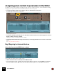


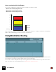


Table Of Contents
- Table of Contents
- Introduction
- Common Operations and Concepts
- On-screen Piano Keys
- Audio Basics
- Sequencer Functions
- About this chapter
- Introduction
- Sequencer area overview
- Track details
- Track definition
- The relationship between the track, the rack and the Main Mixer
- Master Keyboard Input
- The relationship between tracks, lanes, clips and events
- Track types
- Track List elements
- Creating tracks
- Selecting tracks
- Resizing tracks
- Moving tracks
- Deleting tracks
- Duplicating/copying tracks and devices
- Coloring tracks
- Naming tracks
- Folding tracks
- Muting tracks
- Soloing tracks
- Lane details
- Clip basics
- Toolbar details
- Ruler details
- Transport Panel details
- Keys
- Groove
- Q Record
- Quantize value
- Quantize
- Sync Mode
- Song Position
- About subticks in the Song Position display
- Time Position
- Click On/Off
- Pre(-count) On/Off
- Click Level
- Tempo
- Tap Tempo
- Signature
- Rewind and Fast Forward
- Play and Stop
- Record
- Dub and Alt
- Loop On/Off
- Go to Left and Right Locators
- Left and Right Locator Positions
- Transport keyboard commands
- About the Inspector
- Recording in the Sequencer
- About this chapter
- General recording functions
- Audio recording details
- Note recording details
- Parameter automation recording details
- Performance controllers vs. track parameter automation
- Recording performance controller automation
- Recording parameter automation into Note Clips
- Recording performance controller automation over or into an existing clip
- About performance controller automation on multiple lanes
- Recording parameter automation
- Recording parameter automation in Loop mode
- Recording parameter automation over or into an existing clip
- Adjusting automated parameters during playback - “Live mode”
- Recording parameter automation on multiple tracks
- Pattern automation recording details
- Tempo automation recording
- Arranging in the Sequencer
- About this chapter
- Clip handling
- Creating Clips
- Selecting clips
- Setting audio clip Level and Fades
- Deleting clips
- Resizing (masking) clips
- About masked recordings and events
- Tempo scaling clips
- Moving clips
- About overlapping clips
- Duplicating clips
- Cutting, Copying and Pasting clips
- Naming clips
- Coloring clips
- Splitting clips
- Crossfading audio clips
- Joining clips
- Reversing clips
- Muting clips
- Merging clips on note lanes
- Bounce in Place
- Matching clips using the “Match Values” function
- Inserting bars
- Removing bars
- Audio Editing in the Sequencer
- About this chapter
- Edit Modes, Stretch & Transpose Types and Clip Types
- Editing audio in Slice Edit mode
- Editing audio in Pitch Edit mode
- Pitch Editor elements
- Selecting notes
- Auditioning notes
- Correcting pitches
- Changing transposition
- Resetting pitches
- Splitting the clip at notes
- Reverting all notes
- Attenuating pitch drift/vibrato
- Editing transition times
- Moving notes and changing note lengths
- Quantizing notes
- Splitting and joining notes
- About switching from Pitch Edit mode to Slice Edit mode
- Audio pitch editing in the Inspector
- Editing audio in the Comp Editor
- Audio clip elements in the Comp Editor
- The relationship between Clips, Comp Rows and Recordings
- Comp Editor window handling
- Comp Editor audio editing tools
- Selecting a Comp Row for playback in a Single Take clip
- Selecting Comp Rows
- Deleting Comp Rows
- Moving Comp Rows
- Duplicating Comp Rows
- Cutting, copying and pasting Comp Rows
- Adjusting the Comp Row Level
- Adjusting the Recording Offset
- Comping audio
- Common audio editing functions
- Changing the tempo and transposition of the audio
- Audio and tempo matching
- Editing audio using the Inspector
- Note and Automation Editing
- About this chapter
- The Edit Mode
- Tool Window editing tools
- Note editing
- Selecting notes
- Drawing notes
- Deleting notes
- Resizing notes
- Muting notes
- Splitting notes
- Moving notes
- Moving notes manually
- About moving notes outside or between clips
- Changing note pitches (transpose) with the arrow keys
- Nudging note positions with the arrow keys
- About nudging notes outside an open clip
- Moving notes with the “Alter Notes” function
- Moving notes with the “Extract Notes to Lanes” and “Explode” functions
- Moving notes in the Inspector
- Duplicating notes
- Using Cut, Copy and Paste
- Quantize
- Pitch (Transpose)
- Extract Notes to Lanes
- Scale Tempo
- Editing note velocity
- Reverse
- Multi Lanes editing
- Automation editing
- Overview
- Editing parameter automation
- Drawing parameter automation events
- Creating curves between automation points
- Deleting automation events
- Reversing automation events
- Editing performance controller automation
- About Automation Cleanup
- Editing pattern automation
- Drawing pattern automation
- Moving, resizing and duplicating pattern automation clips
- Deleting pattern automation clips
- The “Convert Pattern Automation to Notes” function
- Editing tempo automation
- About tempo changes and tempo automation of audio tracks
- Automating time signature
- Moving, resizing and duplicating time signature automation clips
- Deleting time signature automation clips
- Note and automation editing in the Inspector
- Working with Blocks in the Sequencer
- About this chapter
- Introduction
- Arrangement Views
- Editing Blocks in the Block View
- Arranging Blocks in the Song View
- Working with the Rack
- About this chapter
- Rack device procedures
- Navigating in the rack
- Resizing and detaching the rack
- About Device Groups
- Creating devices
- Selecting devices
- Deleting devices
- Re-ordering devices
- Re-routing devices
- Creating new rack columns
- About the “Sort Selected Device Groups” function
- Replacing devices
- Duplicating devices
- Cut, Copy and Paste devices
- Naming devices
- Folding and unfolding devices
- Working with Players
- Working with Rack Extensions
- Working with VST Plugins
- About this chapter
- About VST plugins
- Installing and enabling VST plugins
- Using VST plugins in Reason
- The Plugin Rack Device
- Front panel
- Rear panel
- About auto-routing of VSTs in the rack
- The Plugin Window
- Editing the VST parameters
- Automating VST parameters
- CV modulation of VST parameters
- Remote controlling VST parameters
- Selecting VST programs
- About saving songs that contain VSTs
- Combining VST plugins in Combinator devices
- About missing VST plugins
- Managing VST plugins
- Sounds, Patches and the Browser
- About this chapter
- About patches
- About ReFills
- Using the Browser
- Opening the browser
- Browser elements
- Navigating in the Browser
- Using Locations and Favorites
- Favorites Lists
- Selecting and auditioning samples and REX loops
- Selecting multiple files
- Cross-browsing patch files
- Create Instrument/Create Effect
- About patch formats and sampler devices
- Using the “Search” function
- Loading files
- About browse lists
- Handling Missing Sounds
- Reason file formats
- Routing Audio and CV
- About this chapter
- Signal types
- About cables
- Automatic routing
- Manual routing
- Using CV and Gate
- The Main Mixer
- About this chapter
- Overview
- Navigating in the Main Mixer
- Managing mixer channels
- The channel strip
- The Master Section strip
- Automating mixer parameters
- Working with effects
- Output Busses
- Parallel Channels
- Solo, Mute and Send FX logic
- Remote controlling the Main Mixer
- Advanced routing tips and tricks
- Delay Compensation
- About this chapter
- About Delay Compensation in Reason
- How the Delay Compensation works
- Delay Compensation in individual mixer channels
- Delay Compensation with Busses and Parallel Channels
- Delay Compensation to Send FX busses
- About the Master Insert FX
- Problematic configurations
- About using the Direct Out connections of the mixer channels
- About the Metronome Click
- Recording with Delay Compensation
- Playing and monitoring with Delay Compensation
- About bouncing mixer channels
- Song File Handling
- Importing and Exporting Audio
- Sampling
- The ReGroove Mixer
- Remote - Playing and Controlling Devices
- About the various MIDI inputs
- About Remote
- Setting up
- Remote basics
- Locking a surface to a device
- Remote Override
- Additional Remote Overrides...
- Keyboard Control
- Saving Remote Setups
- Synchronization and Advanced MIDI
- About this chapter
- Synchronization to MIDI Clock
- Synchronization using Ableton Link
- Advanced MIDI - The External Control Bus inputs
- Optimizing Performance
- Introduction
- Optimization and latency reduction
- Optimizing your computer system
- Optimizing Songs
- Global
- Main Mixer
- Sample Players – NN19, NNXT, Dr. Octo Rex, Grain and Redrum
- Filters – Subtractor, Thor, Malström, NN19, NNXT, Grain, Europa and Dr. Octo Rex
- Polyphonic Devices – Subtractor, Thor, Malström, NN19, NNXT, Grain, Europa, Dr. Octo Rex and Redrum
- Subtractor
- Thor
- Malström
- Redrum
- Mixer devices
- Distortion
- Reverb
- Send Effects
- RAM requirements
- Hardware Interface
- Kong Drum Designer
- Introduction
- Overview
- About file formats
- Using patches
- Pad Settings
- The Drum and FX section
- The Drum modules
- The Support Generator modules
- The FX modules
- Connections
- Using Kong as an effect device
- Using external effects with Kong
- Redrum Drum Computer
- Introduction
- Sampling in Redrum
- About file formats
- Using patches
- Programming patterns
- Redrum parameters
- Using Redrum as a sound module
- Connections
- Dr. Octo Rex Loop Player
- Introduction
- About REX file formats
- Loading and saving Dr. Octo Rex patches
- Playing Loops
- Adding Loops
- Playing individual Loop Slices
- Creating sequencer notes
- Slice handling
- Dr. Octo Rex panel parameters
- Dr. Octo Rex synth parameters
- Connections
- Europa Shapeshifting Synthesizer
- Introduction
- Panel overview
- Signal flow
- Playing and using Europa
- Panel reference
- Sound Engines On/Off and Edit Focus section
- The Oscillator section
- The Modifiers section
- The Spectral Filter
- The Harmonics section
- The Unison section
- The User Wave and Mixer section
- The Filter section
- The Amplifier section
- The Envelopes section
- Envelope 1, 2, 3 and 4
- Preset
- Adding a Sustain stage
- Adding and removing envelope points
- Changing the envelope curve shape
- Looping the envelope
- Editing levels only
- Creating “free form” envelope curves
- Using the Envelope 3 and Envelope 4 curves as Sound Engine waveforms
- Using the Envelope 4 curve as a Spectral Filter curve
- The LFO section
- The Effects section
- The Modulation Bus section
- Connections
- Tips and Tricks
- Grain Sample Manipulator
- Mimic Creative Sampler
- Introduction
- Panel overview
- Signal flow
- Playing and using Mimic
- Panel reference
- Connections
- Tips and Tricks
- Thor Polysonic Synthesizer
- Subtractor Synthesizer
- Malström Synthesizer
- Monotone Bass Synthesizer
- ID8 Instrument Device
- Rytmik Drum Machine
- Radical Piano
- Klang Tuned Percussion
- Pangea World Instruments
- Humana Vocal Ensemble
- NN-XT Sampler
- Introduction
- Sampling in NN-XT
- Panel overview
- Loading complete Patches and REX files
- Using the main panel
- Overview of the Remote Editor panel
- About Samples and Zones
- Selections and Edit Focus
- Adjusting parameters
- Managing Zones and Samples
- Working with Grouping
- Working with Key Ranges
- Setting Root Notes and Tuning
- Using Automap
- Layered, crossfaded and velocity switched sounds
- Using Alternate
- Sample parameters
- Group parameters
- Synth parameters
- Connections
- NN-19 Sampler
- Introduction
- General sampling principles
- About audio file formats
- Sampling in NN-19
- About Key Zones and samples
- Loading a Sample into an empty NN-19
- Loading SoundFont samples
- Loading REX slices as samples
- Creating Key Zones
- Selecting Key Zones
- Setting the Key Zone Range
- Deleting a Key Zone
- About Key zones, assigned and unassigned samples
- Adding sample(s) to a Key Map
- Setting the Root Key
- Removing sample(s) from a Key Map
- Removing all unassigned samples
- Rearranging samples in a Key Map
- Setting Sample Level
- Tuning samples
- Looping Samples
- About the Solo Sample function
- Automap Samples
- NN-19 synth parameters
- Play Parameters
- Connections
- MIDI Out Device
- Quartet Chorus Ensemble
- Sweeper Modulation Effect
- Alligator Triple Filtered Gate
- Pulveriser
- The Echo
- Scream 4 Sound Destruction Unit
- BV512 Vocoder
- Introduction
- Setting up for basic vocoding
- Using the BV512 as an equalizer
- BV512 parameters
- Connections
- Automation
- Tips and tricks
- RV7000 Mk II Advanced Reverb
- Neptune Pitch Adjuster and Voice Synth
- Introduction
- Overview and basic concepts
- Setting up for pitch processing
- Using pitch correction
- Using pitch shifting (Transpose)
- Using Formant control
- Using the Voice Synth
- Panel parameters
- Connections
- Pitch adjustment tips and tricks
- Softube Amps
- Audiomatic Retro Transformer
- Channel Dynamics Compressor & Gate
- Channel EQ Equalizer
- Master Bus Compressor
- Synchronous Timed Effect Modulator
- The MClass Effects
- Half-Rack Effects
- The Combinator
- Introduction
- Combinator overview
- Creating a Combinator device
- About internal and external audio connections
- Adding devices to a Combi
- Combinator handling
- Sequencer tracks and playing Combis
- Configuring the Combinator panel
- Assigning panel controls to parameters in the Editor
- Using Modulation Routing
- CV Connections
- Pulsar Dual LFO
- RPG-8 Arpeggiator
- Matrix Pattern Sequencer
- Mixer 14:2
- The Line Mixer 6:2
- Menu and Dialog Reference
- Reason menu (macOS)
- File menu
- New
- New from Template
- Open...
- Open Demo Song
- Close
- Save
- Save As...
- Save and Optimize
- Song Information...
- Song Self-contain Settings...
- Import Audio File...
- Import MIDI File...
- Export MIDI File...
- Export Insert FX Patch...
- Save Device Patch As...
- Export Song/Loop as Audio File...
- Bounce Mixer Channels...
- Export REX as MIDI File...
- Export Device Remote Info...
- Recent Songs list
- Exit (Windows)
- Edit menu
- Undo
- Redo
- Cut/Cut Tracks and Devices/Cut Channels and Tracks
- Copy/Copy Tracks and Devices/Copy Channels and Tracks/Copy Patch
- Paste/Paste Tracks and Devices/Paste Channels and Tracks/Paste Patch
- Delete/Delete Tracks and Devices/Delete Channels and Tracks
- Delete Tracks
- Duplicate Tracks and Devices/Duplicate Channels and Tracks
- Select All/Select All Devices/Select All Tracks/Select All Channels
- Select All in Device Group
- Sort Selected Device Groups
- Auto-route Device
- Disconnect Device
- Combine/Uncombine
- Copy/Paste Channel Settings (Main Mixer channel strips)
- Route to (Main Mixer channel strips)
- Create Parallel Channel (Main Mixer channel strips)
- Clear Insert FX
- Reset All Channel Settings (Main Mixer channel strips)
- Reset Device
- Cut Pattern
- Copy Pattern
- Paste Pattern
- Clear Pattern
- Browse Patches...
- Browse Loops...
- Browse Samples...
- Automap Samples
- Delete Sample/Remove Sample
- Delete Unused Samples
- Split Key Zone
- Delete Key Zone
- Reload Samples
- Add Zone
- Copy Zones
- Paste Zones
- Duplicate Zones
- Delete Zones
- Select All Zones
- Copy Parameters to Selected Zones
- Sort Zones by Note
- Sort Zones by Velocity
- Group Selected Zones
- Set Root Notes from Pitch Detection
- Automap Zones
- Automap Zones Chromatically
- Create Velocity Crossfades
- Copy Loop to Track
- Copy Pattern to Track
- Shift Pattern Left/Right
- Shift Drum Left/Right
- Shift Pattern Up/Down
- Random Sequencer Pattern
- Randomize Pattern
- Randomize Drum
- Alter Pattern
- Alter Drum
- Invert Pattern
- Arpeggio Notes to Track
- Create Track for.../Delete Track for...
- Go To Track for
- Insert Bars Between Locators
- Remove Bars Between Locators
- Edit
- Bounce in Place
- Bounce Clips to New Samples (Audio Clips)
- Bounce Clip to Disk... (Audio Clips)
- Bounce Clips to New Recordings (Audio Clips)
- Bounce Clip to REX Loop (Single Take Audio Clips)
- Bounce Audio Clips to MIDI
- Stretch and Transpose Type
- Correct Pitch (Audio in Pitch Edit Mode)
- Reset Pitch (Audio in Pitch Edit Mode)
- Split At Slices (Single Take Audio Clips)
- Split At Notes (Single Take Audio Clips)
- Revert Slices (Single Take Audio Clips)
- Revert Notes (Notes in Single Take Audio Clips in Pitch Edit Mode)
- Enable/Disable Stretch (Audio Clips)
- Delete Unused Recordings (Audio Clips)
- Heal Clip Safe Clips (Audio Clips)
- Delete Clip Safe Audio (Audio Clips)
- Normalize Clips (Audio Clips)
- Reverse
- Stretch Type for New Recordings
- Convert Pattern Automation to Notes
- Convert Block Track to Song Clips
- Commit to Groove
- New Note Lane
- Merge Note Lanes on Tracks
- Get Groove From Clip
- Join Clips
- Mute Clips/Unmute Clips
- Crop Events to Clips
- Add Labels to Clips/Remove Labels from Clips
- Clip Color
- Channel Color/Track Color
- Set Loop to Selection
- Set Loop to Selection and Start Playback
- Adjust Alien Clips to Lane
- Select Notes of Same Pitch
- Move/Duplicate Selected Notes to New Lane
- Quantize
- Crossfade
- Edit Sample
- Duplicate Sample(s)
- Export Sample(s)
- Delete Sample(s)
- Edit Keyboard Control Mapping...
- Clear Keyboard Control Mapping
- Clear All Keyboard Control Mappings for Device
- Edit Remote Override Mapping...
- Clear Remote Override Mapping
- Clear All Remote Override Mappings for Device
- Copy/Paste Remote Override Mappings
- Go to Product Page...
- Preferences – General
- Mouse Knob Range
- Automation Cleanup Level
- Trigger Notes while Editing
- Return to last start position on stop
- Reduce Cable Clutter Setting
- Cable animation
- Show parameter value tool tip
- Show automation indication
- Theme
- Default song
- Load last song on startup
- New devices get browse focus
- Load default sound in new devices
- Self-contain samples when loading from disk
- Open Companion on Startup (available in Reason+ only)
- Preferences – Audio
- Master tune
- Audio card driver – Windows
- Audio device – macOS
- Sample rate
- Buffer size
- Input and Output latency
- Recording latency compensation
- Active input and output channels
- Clock source (ASIO Only)
- Control panel
- Use multi-core audio rendering
- Use hyper-threading audio rendering
- Render audio using audio card buffer size setting
- Monitoring
- Play in background
- Preferences – MIDI
- Preferences – Sync
- Preferences – Folders
- Preferences – Advanced
- Create menu
- Options menu
- Internal/MIDI Clock/Ableton Link/Send MIDI Clock
- Enable Keyboard Control
- Keyboard Control Edit Mode
- Remote Override Edit Mode
- Additional Remote Overrides...
- Surface Locking...
- Toggle Rack Front/Rear
- Reduce Cable Clutter
- Auto-group Devices and Tracks
- Delay Compensation
- Show CPU Load for Devices
- Show Navigators
- Always Show Tutorial Area
- Application Zoom
- Follow Song
- Show Block Clip Content in Song View
- Keep Events in Clip while Editing
- Auto-color Tracks and Channels
- Record Automation into Note Clip
- Number of Precount Bars
- MIDI: Send All Notes Off
- Enter/Exit Edit Mode
- Enable Blocks
- Switch to Block View/Song View
- Window menu (Windows version)
- Stay on top
- View Main Mixer
- View Racks
- View Sequencer
- Detach/Attach Main Mixer
- Detach/Attach Rack Window
- View All
- Manage Content
- Rack Extensions
- Manage Plugins
- Show/Hide Browser
- Show/Hide Tutorial
- Show/Hide Transport
- Show/Hide ReGroove Mixer
- Show/Hide Tool Window
- Show/Hide On-screen Piano Keys
- Show Spectrum EQ Window
- Show/Hide Recording Meter
- Show Missing Sounds window
- Open Song Windows list
- Window menu (macOS version)
- Minimize
- Zoom
- Bring All to Front
- View Main Mixer
- View Racks
- View Sequencer
- Detach/Attach Main Mixer
- Detach/Attach Rack Window
- View All
- Manage Content
- Rack Extensions
- Manage Plugins
- Show/Hide Browser
- Show/Hide Tutorial
- Show/Hide Transport
- Show/Hide ReGroove Mixer
- Show/Hide Tool Window
- Show/Hide On-screen Piano Keys
- Show Spectrum EQ Window
- Show/Hide Recording Meter
- Show Missing Sounds window
- Open Song Windows list
- Help menu
- Reason Help...
- Documentation in pdf format...
- Tutorials on the Reason Studios Website...
- Download more Demo Songs...
- Download more Template Songs...
- Go to the Reason Studios Website...
- Check for Updates...
- Your Products... (Windows only)
- Get more Instruments, Sounds & Effects
- Go to Product Page...
- About Reason (Windows only)
- Key Commands
- About the Key Commands chapter
- General keyboard shortcuts
- General modifier keys
- Transport keyboard shortcuts
- Sequencer keyboard shortcuts
- Sequencer modifier keys
- Arrow keys
- Save dialog keyboard shortcuts
- On-screen Piano Keys keyboard shortcuts
- NN-19 modifier keys
- NN-XT keyboard shortcuts
- NN-XT modifier keys
- Dr. Octo Rex keyboard shortcuts
- Dr. Octo Rex modifier keys
- Redrum keyboard shortcuts
- Redrum modifier keys
- Kong modifier keys
- Matrix keyboard shortcuts
- Matrix modifier keys
- RPG-8 keyboard shortcuts
- MIDI Out Device keyboard shortcuts
- Europa modifier keys
- Grain modifier keys
- Sweeper modifier keys
- Mimic modifier keys
- About the Key Commands chapter
- Index

THE COMBINATOR1325
About Rotary/Slider and Switch controls
The virtual Rotary/Slider and Switch controls operate much like the equivalent controls on the real devices:
• A Rotary/Slider control can either smoothly change parameter values (e.g. a level control), or step through
fixed values (like the Oscillator waveform spin controls on a Subtractor).
• A Switch control will switch between two set values like an on/off switch.
Worth noting is that there are buttons on several Reason devices that will step through a series of values, for ex-
ample LFO Waveform buttons. If LFO Waveform is assigned to one of the virtual Buttons you will only be able to
switch between two of the six LFO waveforms (which waveforms is determined by the Min/Max range).
• The available range for each selected parameter is shown in the Modulation Routing Min/Max fields.
Most sliders and rotary knobs on the actual devices have the standard 0-127 or -64 to 63 range. Selectors and
spin controls can have any value range.
About the CV Inputs
On the back of the Editor panel are CV Modulation Inputs for connecting external CV signals to modulate any of the
parameters that are accessible in the Target section in the Editor, see “Wheel CV In and Source CV In”.
Assigning panel controls to device parameters
Assigning Combinator panel controls to device parameters can be done in two different ways:
1. Right click the desired device parameter and select the desired Combinator panel control to assign it to from
the “Map to Combi Control” pop-up:
Assigning the “Master Volume” control on an Europa device to the “Level” control on the Combinator panel.
If you chose the method described above you can continue directly to step 4 below in this description.