VTRAK J610S, J310S PRODUCT MANUAL Version 1.
VTrak J610s, J310s Product Manual Copyright © 2007 Promise Technology, Inc. All Rights Reserved. Copyright by Promise Technology, Inc. (Promise Technology). No part of this manual may be reproduced or transmitted in any form without the expressed, written permission of Promise Technology. Trademarks Promise, and the Promise logo are registered in U.S. Patent and Trademark Office. All other product names mentioned herein may be trademarks or registered trademarks of their respective companies.
Contents Chapter 1: Introduction . . . . . . . . . . . . . . . . . . . . . . . . . . . . . . . . . . . . .1 About This Manual . . . . . . . . . . . . . . . . . . . . . . . . . . . . . . . . . . . . . . .1 Overview . . . . . . . . . . . . . . . . . . . . . . . . . . . . . . . . . . . . . . . . . . . . . .2 Architectural Description . . . . . . . . . . . . . . . . . . . . . . . . . . . . . . . . . .4 Features and Benefits . . . . . . . . . . . . . . . . . . . . . . . . . . . . . . . . . . .5 Specifications .
VTrak J610s, J310s Product Manual Chapter 3: Management, cont. CLI Command Set, cont. Viewing Link Status . . . . . . . . . . . . . . . . . . . . . . . . . . . . . .40 Clearing the Error Count . . . . . . . . . . . . . . . . . . . . . . . . . . .42 Route Command . . . . . . . . . . . . . . . . . . . . . . . . . . . . . . . . . . . .42 Route Troubleshooting . . . . . . . . . . . . . . . . . . . . . . . . . . . .43 Uptime Command . . . . . . . . . . . . . . . . . . . . . . . . . . . . . . . . . . .
Chapter 1: Introduction • About This Manual (below) • Overview (page 2) • Architectural Description (page 4) • Features and Benefits (page 5) • Specifications (page 6) Thank you for purchasing Promise Technology’s VTrak J610s or J310s external disk array subsystem. About This Manual This Product Manual describes how to setup, use and maintain the VTrak J610s or J310s external disk subsystem. It also describes how to use the built-in command-line interface (CLI) software.
VTrak J610s, J310s Product Manual Overview The Promise VTrak J610s and J310s are optimized for organizations deploying cost-effective small-to-medium application clusters, disk-to-disk backup and midrange storage solutions. Figure 1. VTrak J610s front view Drive Carrier LEDs Drive Carriers Power and Status LEDs Figure 2.
Chapter 1: Introduction Figure 3. VTrak J610s rear view I/O module 1 I/O module 2 115200 8N1 Power Supply 1 115200 8N1 Cooling Unit 1 Cooling Unit 2 Power Supply 2 Figure 4.
VTrak J610s, J310s Product Manual Architectural Description The VTrak J610s packs up to 16 drives per system, offering industry-leading capacity in just 3U of standard 19-inch rack space. The VTrak J310s supports up to 12 drives per system, in just 2U of standard 19-inch rack space. The J610s and J310s unit’s compact form factor maximizes density, increasing capacity per unit of rack space.
Chapter 1: Introduction Features and Benefits Feature Benefit 3U or 2U 19-inch wide enclosure Installs easily in any standard rackmount. Supports Serial Attached SCSI disk drives Allows you to use the new dual-port SAS disk drives. Supports Serial ATA disk drives Allows you to use your legacy SATA disk drives. Hot-swap feature for drive carriers, Allows a defective component to be I/O modules, power supplies and replaced without interrupting data fans accessibility to the host system.
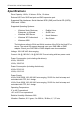
VTrak J610s, J310s Product Manual Specifications Drive Capacity: J610s, 16 drives. J310s, 12 drives. External I/O Ports: SAS host port and SAS expansion port. Supported Disk Interfaces: Serial Attached SCSI (SAS) and Serial ATA (SATA), 3Gb/s and 1.
Chapter 1: Introduction Dimensions (H x W x D): J610s, 13.1 x 44.7 x 56.1 cm (5.2 x 17.6 x 22.1 in) J310s, 8.8 x 44.7 x 56.1 cm (3.5 x 17.6 x 22.1 in) Net Weight: J610s, 30.5 kg (67.2 lb) without drives, 38.5 kg (84.9 lb) with 16 drives, assuming 0.5 kg (1.1 lb) per drive. J310s, 26.5 kg (58.4 lb) without drives, 32.5 kg (71.7 lb) with 12 drives, assuming 0.5 kg (1.1 lb) per drive. Gross Weight (including carton): J610s, 37.5 kg (82.7 lb) without drives. J310s, 33.0 kg (72.8 lb) without drives.
VTrak J610s, J310s Product Manual IRAM Statement Advertencia: Este es un producto de clase A. En un ambiente doméstico, este producto puede causar interferencia de las ondas de radio, en cuyo caso se podría requerir que el usuario tome las medidas adecuadas.
Chapter 2: Installation • Unpacking the VTrak (below) • Mounting VTrak J610s in a Rack (page 11) • Mounting VTrak J310s in a Rack (page 13) • Installing Disk Drives (page 16) • Setting Up Data Cable Connections (page 20) • Setting Up Serial Cable Connections (page 27) • Connecting the Power (page 28) • Setting Up the CLI Connection (page 29) Unpacking the VTrak The VTrak J610s or J310s box contains the following items: • VTrak J610s or J310s Unit • Quick Start Guide • Front bezel and ke
VTrak J610s, J310s Product Manual Figure 1. VTrak J610s rear view I/O module 1 I/O module 2 115200 8N1 Power Supply 1 115200 8N1 Cooling Unit 1 Cooling Unit 2 Power Supply 2 Figure 2. VTrak J310s rear view Cooling Unit 1 Cooling Unit 2 Power Supply 2 Power Supply 1 O O I I 115200 8N1 115200 8N1 I/O module 2 I/O module 1 Some VTraks ship with a single I/O module and a blank unit installed in the place of the second I/O module. You can upgrade your VTrak by installing a second I/O module.
Chapter 2: Installation Mounting VTrak J610s in a Rack The J610s subsystem installs to the rack using the supplied mounting rails. You can also use your existing rails. Figure 3. VTrak J610s mounted in a rack with the supplied rails Vertical Rack Post VTrak J610s Mounting rails (included) mount outside the rack post Handles mount outside the rack post Cautions • At least two persons are required to safely lift, place, and attach the VTrak subsystem into a rack system.
VTrak J610s, J310s Product Manual 4. Square the rail assemblies in the rack. 5. Tighten the adjustment screws and the attaching screws. 6. Place the VTrak subsystem onto the rails. 7. Secure the VTrak subsystem to the rack through each handle, using the attaching screws from your rack system. Figure 4.
Chapter 2: Installation Mounting VTrak J310s in a Rack The J310s subsystem installs to the rack using the supplied mounting rails. You can also use your existing rails. Figure 5. VTrak J310s mounted in a rack with the supplied rails VTrak J310s Vertical Rack Post Handles mount outside the rack post Mounting rails (included) mount outside the rack post Cautions • At least two persons are required to safely lift, place, and attach the VTrak subsystem into a rack system.
VTrak J610s, J310s Product Manual The rail is designed to slide freely over the plate. 5. Attach a flange to each end of the rail, with the rail on the opposite side of the flange from the two-hole bracket. 6. Install the rail adjustment screws (included) through the flange into the rail. There are four screws for each flange. See Figure 7. 7. Place the subsystem with mounting rails into your rack system. 8.
Chapter 2: Installation Figure 7.
VTrak J610s, J310s Product Manual Installing Disk Drives Populate the VTrak with 3.5-inch SAS or SATA disk drives. Install all of the drive carriers into the VTrak enclosure to ensure proper airflow, even if you do not populate all the carriers with disk drives. Caution Use only the counter-sink screws supplied with the VTrak. Use of other types of screws can damage the enclosure or the adjacent drives. Figure 8. Drive carrier mounting holes Counter-sink screws only.
Chapter 2: Installation If you installed an AAMUX, lay the SATA disk drive in the carrier and slide it so the power and data connectors insert in to the AAMUX. See Figure 10. 5. Insert the screws through the holes in the drive carrier and into the bottom of the disk drive. See Figure 8. • Install only the screws supplied with the VTrak. • Install four screws per drive. • Snug each screw. Be careful not to over tighten. 6. Reinstall the drive carrier into the VTrak chassis. 7.
VTrak J610s, J310s Product Manual Figure 10.Drive carrier with SATA disk drive and AAMUX SATA Disk Drive AAMUX adapter SAS connector Cautions • If you plan to operate your VTrak with fewer than a full load of disk drives, install all of the drive carriers into the enclosure, to ensure proper airflow for cooling. • A VTrak J610s or J310s carrier is similar in appearance but is NOT interchangeable with a VTrak M500f/i/p drive carrier. Important Be sure each drive is securely fastened to its carrier.
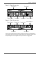
Chapter 2: Installation Drive Numbering Each disk drive in the J610s or J310s unit is identified by a number that corresponds to the Port number used for management. See “Link Command” on page 40. Numbers are stamped above each drive bay for easy identification. Figure 11.VTrak J610s drive slot numbering 1 2 3 5 4 6 9 10 13 8 7 11 12 15 14 16 Figure 12.
VTrak J610s, J310s Product Manual Setting Up Data Cable Connections VTraks provide Direct Attached Storage (DAS) support to the Host PC. Figure 13. VTrak J610s has one or two I/O modules I/O module 1 (default primary) I/O module 2 115200 8N1 115200 8N1 Figure 14.VTrak J310s has one or two I/O modules O O I I 115200 8N1 115200 8N1 I/O module 1 (default primary) I/O module 2 There can be one or two Input Output Modules (I/O modules) on the VTrak.
Chapter 2: Installation Figure 15.I/O modules have a circle-icon port and a diamond-icon port 115200 8N1 Diamond-icon port (CN2) LED Circle-icon port (CN1) LED I/O Module Status LED Each I/O module has one circle-icon port and one diamond-icon port. In the CLI command set, the circle-icon port is called CN1 and the diamond-icon port is called CN2. See “CLI Command Set” on page 35. Note SAS HBA cards are User-supplied items. They are not included with the VTrak unit.
VTrak J610s, J310s Product Manual Basic DAS Connection Figure 16. An example of a basic DAS connection between one Host PC and one VTrak J310s unit. The J610s is similar Connect to either data port O O I I 115200 8N1 115200 8N1 VTrak J310s SFF-8088 external 4X to 4X SAS cable SAS HBA Card PC The arrangement above is the minimum DAS system with a single SAS HBA card in the Host PC. Connect the SAS HBA card to either port of the I/O module on the VTrak.
Chapter 2: Installation Cascading DAS Connection If you have multiple VTraks and want to manage them from the same SAS HBA card in the Host PC, connect the VTraks in a cascade. See Figure 17. To setup a cascading DAS connection: 1. Connect the SAS HBA card in the Host PC to either of the SAS ports, circleor diamond-icon) on the I/O module of the first VTrak. Use a SFF-8088 4X to 4X external SAS cable (supplied with the VTrak). 2.
VTrak J610s, J310s Product Manual Figure 17. Two examples of cascaded DAS connections between one Host PC and two VTrak J310s units.
Chapter 2: Installation Redundant DAS Connection A fully redundant arrangement requires: • Two VTrak J610s or J310s units with dual I/O modules • Two Host PCs with a SAS HBA card in each PC Each HBA card connects to a different I/O module in the first VTrak, to provide a separate cascade. See Figure 18. To setup a redundant DAS connection: 1. Connect the SAS HBA card in the first Host PC to either of the SAS ports, circle- or diamond-icon) on the first I/O module of the first VTrak.
VTrak J610s, J310s Product Manual Figure 18. An example of a redundant DAS connection between two Host PCs and four cascaded VTrak J310s units.
Chapter 2: Installation Setting Up Serial Cable Connections Serial communication enables the Command Line Interface (CLI) on your PC to monitor to control the VTrak. The VTrak package includes one RJ11-to-DB9 serial data cable for each I/O module. Figure 19. A serial connector is located on the I/O module. The J310s is shown. The J610s is similar RJ11 Serial Connector 115200 8N1 O O I I 115200 8N1 115200 8N1 To set up a serial cable connection: 1.
VTrak J610s, J310s Product Manual Connecting the Power Plug the power cords and switch on both power supplies. When the power is switched on, the LEDs on the front of the VTrak will light up. Figure 20.VTrak J310s front panel LED display.
Chapter 2: Installation Setting Up the CLI Connection The VTrak has a Command Line Interface (CLI) to manage all of its functions, including customization. Access the CLI via your PC’s terminal VT100 or ANSI emulation program, such as Microsoft HyperTerminal. With the VTrak running and the RJ11-to-DB9 serial data cable connected to the primary I/O module: 1. 2. 3.
VTrak J610s, J310s Product Manual 30
Chapter 3: Management • Front Status Indicators (below) • Drive Status Indicators (page 24) • I/O Module Status Indicators (page 25) • CLI Command Set (page 26) Front Status Indicators Even though the Command Line Interface (CLI) offers comprehensive monitoring of VTrak, the LED indicators on the VTrak J610s or J310s unit provide important status information. When the power is switched on, the LEDs on the front of the VTrak will light up. Figure 1. VTrak J310s front panel LED display.
VTrak J610s, J310s Product Manual State LEDs Dark Steady Green Power System Off Normal FRU* System Off Normal Flashing Green Red 1 CU and/or 1 PSU failed I/O Module No Activity 1 or 2 Activity Heartbeat Normal** System Off Amber 2 CU and/or 2 PSU failed * Field Replacement Unit: Cooling Unit (CU) or Power Supply Unit (PSU) ** Blinks intermittently. Drive Status Indicators After a few moments the Power/Activity should display Green.
Chapter 3: Management State LEDs Dark Steady Green Drive Present Flashing Green Power/Activity* No Drive Status HBA/RAID controller determines the LED behavior** Activity * Refers to SAS drives or SATA drives with an AAMUX adapter. For SATA drives without an AAMUX adapter, LED behavior depends on the specific disk drive. ** Refer to the user documentation for your HBA or RAID controller for this information.
VTrak J610s, J310s Product Manual Figure 4. VTrak J610s power supply and fan LEDs Power Supply LED Fan LED The battery LED on the cooling unit has no function on the VTrak J610s and J310s models. Figure 5. VTrak J310s power supply and fan LEDs Power Supply LED Fan LED O I Under normal conditions, the power supply and fan LEDs should display green.
Chapter 3: Management CLI Command Set The CLI uses the following set of commands: cable – Specifies the length of cable for optimal signal quality. enclosure – Displays full information on the VTrak enclosure and all its components, expander addresses, and SAS addresses. help – Use alone to see the list of commands. Use with a command to see a list of options. Examples: enclosure -help or enclosure -h. link – Displays the current status of the PHYs (links) and the error counter.
VTrak J610s, J310s Product Manual The system returns: CN#1 Cable Length = 1 meter CN#2 Cable Length = 3 meter Note the cable length change for CN2.
Chapter 3: Management The system returns: ------------------------------------------------------------------------------------Time Since Power Up: 1 day 9 hours 46 minutes 36 seconds Enclosure: SAS JBOD [2U-12Bay or 3U-16 Bay] I/O Module ID: 1 Max Num Of I/O Modules: 2 FwVersion: 1.07.0000.
VTrak J610s, J310s Product Manual Expander SAS Address: SAS Base Addr:50 00 15 5D 21 AB 02 00 SSP SAS Addr: 50 00 15 5D 21 AB 02 3E SMP SAS Addr: 50 00 15 5D 21 AB 02 3F Attached SAS Address: D01 SAS Addr: 50 00 15 E0 11 4E 5E B2 D02 SAS Addr: 50 00 15 E0 11 4E 80 C2 D03 SAS Addr: 50 00 15 E0 11 4C 22 02 D04 SAS Addr: 50 00 15 E0 11 4D E2 22 D05 SAS Addr: 50 00 15 E0 11 4D 8F B2 D06 SAS Addr: 50 00 15 E0 11 4D D0 62 D07 SAS Addr: 50 00 15 E0 11 4D DE E2 D08 SAS Addr: 50 00 15 E0 11 4D 8E F2 D09 SAS Addr: 5
Chapter 3: Management • Automatic Shutdown – Shuts down the VTrak 30 seconds after the enclosure or controller reaches critical temperature. • Minimum Fan Speed – Specifies the minimum fan speed when the VTrak reaches enclosure or controller warning temperature. Making Settings To set the enclosure critical temperature to 61°C (141°F): cli>enclosure -a mod -s “enc_critical=61” To enable Thermal Management: cli>enclosure -a mod -s “thermalmanager=1” For this command, a 1 enables and a 0 disables.
VTrak J610s, J310s Product Manual To access help with a specific function: cli>help cable cli>cable -help cli>cable -h Choose any command from the list under “CLI Command Set” on page 35.
Chapter 3: Management P22 P23 CN2 CN2 SAS SAS 3.0G 3.0G OK OK End End ------- Rdy Rdy Port:Port Id Type:SAS Rate:Rate 3G Init:Init Passed Dev:Device Type Link:Link Connected PRdy:Phy Ready The following items are reported in the table above: • Link number – The links are PHYs, numbered P0 through P23 • Port number – D01 through D16 represent drive slots. Each slot has one PHY. D13 through D16 are empty on J310s units. See “Drive Numbering” on page 19.
VTrak J610s, J310s Product Manual P20 P21 P22 P23 ------------------------------------- ------------------------------------- ------------------------------------- ------------------------------------- ------------------------------------- 0x8F 0x8F 0x8F 0x8F InDW:Invalid Dword Count DsEr:Disparity Err Count DwLo:Dword Sync Loss Count PhRe:Phy Reset Problem Count CoVi:Code Violations Cnt PhCh:Phy Change Count The following items are reported in the table above.
Chapter 3: Management 0238 0287 500000E01212F582 500000E0120B26B2 CN2 CN2 0365 0462 0468 0542 0624 5000155FFFC0223E 500000E0114F18F2 500000E01205B472 500000E01122C5B2 500000E0114E4A32 CN2 CN2 CN2 CN2 CN2 0639 0700 0721 0751 0764 500000E0114D8E32 500000E0120B2A62 500000E0114DE7A2 500000E0114E5EA2 500000E0120B28F2 CN2 CN2 CN2 CN2 CN2 0765 0977 1023 500000E0114C2342 500000E0120A2472 5000155FFFC02408 CN2 CN2 CN2 The route command displays SAS addresses that are attached to the SAS ports of the J610
VTrak J610s, J310s Product Manual VPDR Command The vpdr command displays vital product data on the major components of the VTrak. There are six components that report vital product information. • 1 – Controller (I/O module) • 2 – Power Supply 1 • 3 – Cooling Unit 1 • 4 – Power Supply 2 • 5 – Cooling Unit 2 • 6 – Backplane Specify the component by its number. For I/O modules, the system reports for the module to which you made your CLI connection.
Chapter 4: Support • Frequently Asked Questions (below) • Contacting Technical Support (page 46) • Limited Warranty (page 49) • Returning product for repair (page 50) Frequently Asked Questions What kind of disk drives can I use with VTrak? The J610s and J310s support 3.5-inch Serial Attached SCSI (SAS) disk drives and SATA II disk drives. If your VTrak has dual I/O modules, you must install an AAMUX adapter on each of your SATAII drives.
VTrak J610s, J310s Product Manual Contacting Technical Support Promise Technical Support provides several support options for Promise users to access information and updates. We encourage you to use one of our electronic services, which provide product information updates for the most efficient service and support. Important Promise offers 24x7 live technical support (in English only) for registered owners of VTrak products. To register, point your browser to: http://www.promise.
Chapter 4: Support The Netherlands E-mail Support e-Support On-Line Fax Support +31 (0) 40 256 9463 Attn: Technical Support Phone Support +31 (0) 40 235 2600 If you wish to write us for support: Promise Technology Europe B.V.
VTrak J610s, J310s Product Manual Taiwan E-mail Support e-Support On-Line Fax Support +886 3 578 2390 Attn: Technical Support Phone Support +886 3 578 2395 (ext. 8811) If you wish to write us for support: Promise Technology, Inc. 2F, No. 30, Industry E. Rd. IX Science-based Industrial Park Hsin-Chu 30075, Taiwan, (R.O.C.
Chapter 4: Support Limited Warranty Promise Technology, Inc. (“Promise”) warrants that for three (3) years from the time of the delivery of the product to the original end user: a) the product will conform to Promise’s specifications; b) the product will be free from defects in material and workmanship under normal use and service.
VTrak J610s, J310s Product Manual No other document, statement or representation may be relied on to vary the terms of this limited warranty. Promise’s sole responsibility with respect to any product is to do one of the following: a) replace the product with a conforming unit of the same or superior product; b) repair the product.
Chapter 4: Support The technician will assist you in determining whether the product requires repair. If the product needs repair, the Technical Support Department will issue an RMA (Return Merchandise Authorization) number. Important Obtain an RMA number from Technical Support before you return the product and write the RMA number on the label. The RMA number is essential for tracking your product and providing the proper service.
VTrak J610s, J310s Product Manual 52
Appendix A: Second I/O Module The VTrak J610s and J310s units ship with one or two I/O modules. If your VTrak came with only one I/O module, you can upgrade by installing a second I/O module. The following instructions describe how to install a second I/O module. To install a second I/O module into a VTrak J610s or J310s unit: 1. Power down the VTrak. 2. Press the release button on the dummy I/O module, pull the handle down and remove the dummy I/O module from the enclosure. 3.
VTrak J610s, J310s Product Manual 54
Index Symbols cooling unit LED ? command 44 D A DAS basic 22 cascade 23 redundant 25 supported 20 Data cable connections 20 Basic DAS 22 Cascading DAS 23 Redundant DAS 25 diamond-icon port 21, 23, 25 Dimensions 7 disk drives drive carriers 18 hot-swappable 45 install 16 numbering 19 supported 16, 45 AAMUX adapter 16, 18, 32 About This Manual 1 Attached SAS addresses 36 automatic shutdown setting 39 B blower status 36 C cable command 35 RJ11-to-DB9 9, 27, 29 SAS SFF-8088 9, 22, 23, CE statement 7 Ce
VTrak J610s, J310s Product Manual O H HBA card 21, 22, 23, 25 Heartbeat LED 28, 31 help command 39 Operating Systems, supported 6 P PHY ready status 41 port circle icon 21, 23, 25 CN1, CN2 21 diamond icon 21, 23, number 41 Power connection 28 LED 28, 31 requirements 6 power supply 10 LED 34 single 45 status 36 primary I/O module 20 I I/O module 10, 27 add second module 53 default primary 20 dual 25 role 36, 45, 53 SAS ports 22, 23, 25 IRAM statement 8 L LEDs cooling unit 34 disk drives 32 drive car
Index serial communication 27 setting automatic shutdown 39 minimum fan speed 39 temperature 38 thermal management 38 SFF-8088 cable 9, 22, 23, 25 Specifications 6 Status Indicators disk drives 32 front 31 I/O module 33 status, PHY 41 U Unpack the VTrak 9 uptime command 43 V vital product data 44 voltage sensors 36 vpdr command 44 VTrak rackmount E310f/s 13 rackmount E610f/s 11 returning for repair 50 unpack 9 warranty 7 T Technical Support 46 temperature sensors 36 settings 38 thermal management set
VTrak J610s, J310s Product Manual 58