ULTRATRAK100 TX4 AND ULTRATRAK100 TX8 USER MANUAL
COPYRIGHT © 2001, Promise Technology, Inc. Copyright by Promise Technology, Inc. (Promise Technology). No part of this manual may be reproduced or transmitted in any form without the expressed, written permission of Promise Technology. TRADEMARKS Promise, and the Promise logo are registered in U.S. Patent and Trademark Office. All other product names mentioned herein may be trademarks or registered trademarks of their respective companies.
RADIO FREQUENCY INTERFERENCE STATEMENT This equipment has been tested and found to comply with the limits for a Class B digital device, pursuant to Part 15 of the FCC Rules. These limits are designed to provide reasonable protection against harmful interference in a residential installation. This equipment generates, uses and can radiate radio frequency energy, and, if not installed and used in accordance with the instruction may cause harmful interference to radio communications.
TABLE OF CONTENTS Introduction .................................................................................................................. 1 Architectural Description......................................................................................... 1 Features and Benefits ............................................................................................ 2 Getting Started .............................................................................................................
Appendix A - Technology Background ....................................................................... 41 Introduction to RAID ............................................................................................. 41 RAID 0 – Striping.................................................................................................. 41 RAID 1 – Mirroring................................................................................................ 42 RAID 0+1 – Striping/Mirror ....................
INTRODUCTION Thank you for purchasing Promise Technology’s UltraTrak100 TX4 or UltraTrak100 TX8 external disk array system. UltraTrak100 provides data storage solutions for applications where fault tolerance and data redundancy are required. The failure of any single drive will not affect data integrity or accessibility of the data. A defective drive may be replaced without interruption of data availability to the host computer.
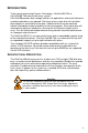
UltraTrak100 TX4 and UltraTrak100 TX8 User Manual FEATURES AND BENEFITS Feature Maximum fault tolerance Supports RAID levels 0, 1, 3, 5, 0+1, and JBOD Emulates standard SCSI-3 drive to host Supports asynchronous and synchronous transfer mode Tagged command queuing up to 32 commands Front panel LCD and LED indicators Hot swap feature Hot-spare drive Automatic background data reconstruction when a drive is replaced Redundant fans Redundant Power Supply (TX8 only) 2 Benefit Ensures uninterrupted data avail
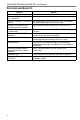
GETTING STARTED Caution To prevent serious damage to the UltraTrak100 be sure that the voltageselect switch on the back of the power supply is set to your local voltage (see Figure 2 on page 5). Getting started with the UltraTrak100 consist of the following steps: 1. 2. 3. 4. 5. 6. 7. Unpack UltraTrak100 storage subsystem (page 3). Install Hard Drives (page 3) Connecting the SCSI Cables (page 5). Connect Power Cable and Switch Power On (page 7). Assign a SCSI ID (page 7).
UltraTrak100 TX4 and UltraTrak100 TX8 User Manual Before installing a new hard drive, be sure the jumpers on the new hard drives are set for single or master operation. Consult the drive manual for the proper settings. Install new hard drives into the UltraTrak100 by doing the following: 1. 2. 3. 4. 5. 6. 7. 8. Open the Front Panel Door on the UltraTrak100. Unlock the Drive Carrier Latching Mechanism and remove an unused Drive Carrier (see Figure 1 on page 4) from the UltraTrak100.
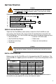
CONNECTING THE SCSI CABLES Installation of the UltraTrak100 disk array is very similar to the installation of a standard SCSI drive. The SCSI connector accepts the standard 68-pin LVD SCSI connector used on most LVD SCSI devices. Refer to your system and/or SCSI host adapter manual for additional installation procedures that may apply to your system or host adapter.
UltraTrak100 TX4 and UltraTrak100 TX8 User Manual (the one which is attached to the SCSI adapter) to the top connector, and place an LVD SCSI active terminator on the other connector. An LVD SCSI active terminator is included with UltraTrak100 disk array unit.
device has a unique SCSI ID and that only the first and last devices are terminated. (See SCSI Cable Connection and Termination on page 5). Terminator SCSI ID WIDE SCSI COM2 Another SCSI Device Computer or Workstation UltraTrak100 TX4 UltraTrak100 TX4 Figure 4. Daisy Chaining UltraTrak100 with Other SCSI Devices CONNECT POWER CABLE AND SWITCH POWER ON The UltraTrak100 TX4 disk array includes a single power supply; The UltraTrak100 TX8 includes two replaceable power supply modules.
UltraTrak100 TX4 and UltraTrak100 TX8 User Manual CONFIGURE THE ULTRATRAK100 The configuration procedures for both the UltraTrak100 TX4 and UltraTrak100 TX8 are exactly the same. The following procedures provide the basic steps needed to create an array and get your UltraTrak100 running quickly. Before beginning, you need to decide if you will create an array using the automatic setup features or if you will create the array manually. Both procedures are provided, but you can only use one of them.
Note If you wish to make a RAID 0+1 array using 4, 6, or 8 drives you need to choose RAID 1 (mirroring) and then follow the steps below to create the array. 9. Press SEL to assign Stripe Block Size. 64KB is the optimum value for most applications. Choosing the proper Stripe Block Size facilitates efficient data flow. You might want to choose a different value if you know the size of the cache buffer in your hard drives or the average data block size of the data you retrieve.
UltraTrak100 TX4 and UltraTrak100 TX8 User Manual For the Gigabyte Boundary feature to work, the Gigabyte Boundary feature must be set to ON when the original array is created. When enabled, the Gigabyte Boundary feature rounds the drive capacity of all drives to the common whole GB drive size. For example, with the Gigabyte Boundary feature enabled, the remaining working drives can be 20.5 GB and the replacement drive can be 20.3, since all are rounded down to 20GB.
Recommended Applications for RAID 1 • • • • Accounting Payroll Financial Any application requiring very high availability RAID 3 Advantages High Read data transfer rate Disk failure has an insignificant impact on throughput Disadvantages Parity drive can become bottleneck if a lot of writes are occurring Recommended Applications for RAID 3 • • • Image Editing Prepress Applications Any application requiring high throughput RAID 5 Characteristics/Advantages High Read data transaction rate Medium Write d
UltraTrak100 TX4 and UltraTrak100 TX8 User Manual JBOD Characteristics/Advantages Uses 100% capacity of all hard drives Disadvantages The failure of just one drive will result in all data in an array being lost Should not be used in mission critical environments Recommended Applications for JBOD • • File archiving General fileserver HOT SPARE DRIVE(S) A good precaution to protecting your array integrity in the event of drive failure is maintaining a hot spare drive.
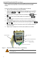
MAINTENANCE DRIVE STATUS INDICATORS As shown in the figure below, each drive has three status LEDs. Figure 5. Location of Drive Status Indicators (TX4 shown) MEANING OF STATUS INDICATORS Indicator Power Status Disk Color Off Green Green Amber Red Off Green Meaning No disk drive power – power off or no disk installed. Disk power on.
UltraTrak100 TX4 and UltraTrak100 TX8 User Manual A non-fault tolerant array goes "offline" when a drive is removed or fails. Since the array is not fault tolerant, the data stored in the array is no longer accessible. If the drive was removed, then it should be replaced to restore accessibility to the array. If the drive failed, then the entire array must be deleted and re-initialized since all data is considered lost.
Reconstruction begins automatically as soon as a replacement drive becomes available to the array. However, if the replacement drive was formerly part of another array, then the previous array information must be deleted (from the replacement drive – see page 29, “Delete Array”, for more details) before reconstruction begins. Attention The electronic components within the UltraTrak100 disk array are sensitive to damage from ESD (Electro-Static Discharge).
UltraTrak100 TX4 and UltraTrak100 TX8 User Manual 9. Insert screws through the holes in the Drive Carrier and into the bottom of the new hard drive. Tighten each screw; be careful not to over tighten. 10. Slide the assembled Drive Carrier back into the UltraTrak100 and lock the Drive Carrier lock. Disk Drive Connect Power Cable to the Disk Drive Connect Drive Data Cable to the Disk Drive Drive Carrier Latching Mechanism Figure 7.
Caution Risk of electrical shock. When either power supply module is removed from the chassis, AC power is accessible at the circuitry in the power supply chassis. Only trained and qualified personnel should remove the power supplies.
UltraTrak100 TX4 and UltraTrak100 TX8 User Manual ULTRATRAK100 FRONT PANEL INTERFACE The front panel interface for the UltraTrak100 consist of following items: UltraTrak100 TX4 ARRAY SCSI BUS SEL Type of Interface LED Indicators Liquid Crystal Display Control Buttons Name Array SCSI Bus Message Display Panel SEL EXIT 18 EXIT Comments Activity Indicator Activity Indicator This is a 24-character by 2-row LCD that displays various setup, status, and error messages.
THE LCD MESSAGES The UltraTrak100 LCD message display panel has the following modes of operation: • • • Idle mode Error mode Configuration mode Idle Mode Error Mode See below Provides an error message Configuration Mode See page 20 View Status Configure Array Configure Cache Configure SCSI See page 21 See page 24 See page 32 See page 33 IDLE MODE The Idle mode message, such as shown below, is displayed during normal operation of the UltraTrak100 when there are no problems or buttons being pressed: A
UltraTrak100 TX4 and UltraTrak100 TX8 User Manual The first line of the Idle mode menu will display one of the following status messages: • Array Functional The array is fully operational, and no problems are present. • Array Critical The array is operational, but has lost its fault tolerance. For RAID array levels 1, 3 and, 5 the array contains a failed drive. The user should identify and replace the failed drive. • Array Offline The array is no longer operational.
View Status View Controller Info See page 22 Memory Size Hardware Rev Firmware Rev View Cache Stats See page 22 Cache Memory Size Cache Block Size Cache Read Hit Cache Write Hit View Array Information See page 23 Array x Size RAID x Status View Enclosure See page 23 Temperature Fan 1 Status Fan 2 Status Fan 3 Status Fan 4 Status VIEW STATUS MENU The View Status menu allows the user to select the information he wishes to view with the following menu: View Controller Info.
UltraTrak100 TX4 and UltraTrak100 TX8 User Manual VIEW CONTROLLER INFORMATION The View Controller Information mode displays UltraTrak100 firmware revision, memory size, and hardware revision: Memory Size: 16 MB Where the values shown are simply examples. Hardware Rev: PDC20265 Firmware Rev: V1.00 B00 Press or to move these items on the LCD. What you can do: Press SEL: Does nothing. Press : Moves the active message line up. Press : Moves the active message line down.
VIEW ARRAY INFORMATION The View Array Information mode displays the array ID, array size, RAID level and array status (Functional, Critical, Offline, Rebuilding and Synchronizing). If these modes of display require more than 2 lines to display information the up and down keys will be used to scroll the display. The Array ID may be 1, 2, 3, or 4 Array: 0 Size: 12GB Where the values shown are simply examples.
UltraTrak100 TX4 and UltraTrak100 TX8 User Manual C o nfig u re Array Auto Array S etup See page 25 Create/Cancel V iew D rive Assignm ents See page 26 Provides a list of installed disk drives. See page 27 D efine Array RAID Level Stripe Block Size GB Boundary Add/Rem ove Drives Save Changes D elete Array See page 29 Provides a list of assigned arrays. Advanced Features W ipeout Disk Synchronize Array Disable Buzzer Rebuild/Sync Pri. Provides a list of installed disk drives.
CONFIGURE ARRAY The Configure Array menu will allow the creation and deletion of arrays. The configure array menu contains the following sub menus: Auto Array Setup View Drive Assignments Define Array Delete Array Advanced Feature What you can do: Press SEL: Press or to move these items on the LCD. Selects one of the following active functions: Auto Array Setup Moves the display to the Auto Array Setup menu. View Drive Assignments Moves the display to the View Drive Assignments menu.
UltraTrak100 TX4 and UltraTrak100 TX8 User Manual You will see the following message if all of the drives are already configured: No Free Disk What you can do: Press SEL: Pressing SEL will save the array. Press : Does nothing. Press : Does nothing. Press EXIT: Press EXIT to cancel this function and return to the Configure Array menu.
DEFINE ARRAY The Define Array menu defines array parameters for the selected array. An array number is selected by using the up/down key to select the array number field. The SEL key is then used to select array number 1-4. The parameter to be configured, RAID Level or Stripe Block size, is then selected with up/down keys. Once the parameter is selected, the value is selected with the up/down keys and then set by hitting the SEL key.
UltraTrak100 TX4 and UltraTrak100 TX8 User Manual STRIPE BLOCK SIZE The Stripe Block Size menu allows you to select a Stripe Block Size between 4KB and 64KB: 4KB 8KB 16KB Press or to move these items on the LCD. … 64KB What you can do: Press SEL: Selects one of the active Stripe Block Size: Press : Moves the active message line up. (Active is marked by *.) Press : Moves the active message line down. (Active is marked by *.) Press EXIT: Returns to the Define Array menu.
ADD/REMOVE DRIVES The Add/Remove Drives menu assigns and removes drives from arrays. All free drives are displayed as one drive per line format. The SEL key toggles the drive between free and assigned. Assigned drives are designated by displaying Assigned and free drives are designated by displaying Free. 1 MAXTOR Free Where the values shown are simply examples. 2 IBM Assigned 3 MAXTOR Free 4 IBM Free What you can do: Press SEL: Press or Toggles the selected drive between Free and Assigned.
UltraTrak100 TX4 and UltraTrak100 TX8 User Manual ADVANCED FEATURE Wipe out disk Synchronize Array Disable Buzzer Rebuild/Sync Pri. What you can do: Press SEL: Press or to move these items on the LCD. Selects one of the following active functions: Wipe out disk Moves the display to the Wipe out disk menu. Synchronize Array Moves the display to the Synchronize Array menu. Disable Buzzer Pressing SEL toggles between Enable and Disable Press : Moves the active message line up.
SYNCHRONIZE ARRAY The Synchronize Array menu allows the user to synchronize the data on each drive. Synchronization is a maintenance procedure for fault tolerant arrays (RAID 1, 0+1, 3 and 5) to maintain data consistency on all drives. To synchronize the array, go to the Configuration menu and select Configure Array; then select Advance Features and choose Synchronize Array. Array ID: 1 Only existing Array IDs are Displayed. Array ID: 2 Press or to move these items on the LCD.
UltraTrak100 TX4 and UltraTrak100 TX8 User Manual Configure Cache Write Cache See below Write Back Write Thru CONFIGURE CACHE The Configure Cache menu will allow the setting of cache parameters. The following parameter is set in the Configure Cache menu: Write Cache What you can do: Press SEL: Write Cache Selects one of the following active functions: Moves the display to the Write Cache menu. Press : Moves the active message line up. (Active is marked by *.
Configure SCSI See below Mode ID LUN SCSI ID See page 34 List SCSI IDs 0 thru 15 to be selected from. CONFIGURE SCSI The Configure SCSI menu will allow the setting of SCSI parameters. The following parameters are set in the configure SCSI menu: Mode SCSI ID What you can do: Press SEL: Selects one of the following active functions: Mode Move the display to the Mode menu. SCSI ID Move the display to the SCSI ID menu. Press : Moves the active message line up. (Active is marked by *.
UltraTrak100 TX4 and UltraTrak100 TX8 User Manual When using ID mode, if you have multiple arrays within an UltraTrak100 unit, each array will use a separate SCSI ID. When using LUN mode, each UltraTrak100 unit will use a single SCSI ID, with the first array being LUN 0, the second array being LUN1, etc. Enable Multiple LUN support in your SCSI adapter if you choose LUN mode. In most cases it is preferable to use ID mode.
CONTACTING PROMISE SUPPORT Promise Technical Support provides several support options for Promise users to access information and updates. We encourage you to use one of our electronic services, which provide product information updates for the most efficient service and support.
UltraTrak100 TX4 and UltraTrak100 TX8 User Manual Pacific Rim Sales Office E-mail Support support@promise.com.tw Fax Technical Support +886 3 578 23 90 Attention: Technical Support Phone Technical Support +886 3 578 23 95 9:00-5:30pm Taiwan Time If you wish to write us for support: Promise Technology, Inc. Attn: Technical Support 2F, No. 30, Industry E. Rd. IX, Science-Based Industrial Park, Hsin-Chu, Taiwan, R.O.C. China Office 36 E-mail Support support-china@promise.
LIMITED WARRANTY Promise Technology, Inc. (Promise Technology) warrants that for two (2) years from the time of the delivery of the product to the original end user: a. the product will conform to Promise Technology’s specifications; b. the product will be free from defects in material and workmanship under normal use and service. This warranty: a. applies only to products which are new and in cartons on the date of purchase; b. is not transferable; c.
UltraTrak100 TX4 and UltraTrak100 TX8 User Manual reprogramming, or reproducing of programs or data stored in or used with the products, or for any other general, special, consequential, indirect, incidental, or punitive damages, whether in contract, tort, or otherwise, notwithstanding the failure of the essential purpose of the foregoing remedy and regardless of whether Promise Technology has been advised of the possibility of such damages. Promise Technology is not an insurer.
RETURNING PRODUCT FOR REPAIR (USA & CANADA) If you suspect a product is not working properly, or if you have any questions about your product, contact our Technical Support Department through one of our technical services. You may reach our Technical Support Department as follows: • Call us at (408) 452-1180 • E-mail us at support@promise.com However, before contacting Technical Support we ask that you first visit our Technical Support web page at http://support.promise.
UltraTrak100 TX4 and UltraTrak100 TX8 User Manual YOUR RESPONSIBILITIES You are responsible for determining whether the product is appropriate for your use and will interface with your equipment without malfunction or damage. You are also responsible for backing up your data before installing any product and for regularly backing up your data after installing the product. Promise Technology is not liable for any damage to equipment or data loss resulting from the use of any product.
APPENDIX A - TECHNOLOGY BACKGROUND INTRODUCTION TO RAID RAID (Redundant Array of Independent Disks) allows multiple hard drives to be combined together to form one large logical drive or “array.” As far as the operating system is concerned, the array represents a single storage device, and treats it as such. The RAID software and/or controller handles all of the individual drives on its own.
UltraTrak100 TX4 and UltraTrak100 TX8 User Manual RAID 1 – MIRRORING When a disk array is mirrored, identical data is written to a pair of drives, while reads are performed in parallel. The reads are performed using elevator seek and load balancing techniques where the workload is distributed in the most efficient manner. Whichever drive is not busy and is positioned closer to the data will be accessed first. With RAID 1, if one drive fails or has errors, the other mirrored drive continues to function.
RAID 0+1 – STRIPING/MIRROR Striping/mirroring combines both of the previous array types. It can increase performance by reading and writing data in parallel while protecting data with duplication. At least four drives are needed for RAID0+1 to be installed. With a four-drive disk array, drive pairs are striped together with one pair mirroring the first pair. The data capacity is similar to a standard mirroring array, with half of the total storage capacity dedicated for redundancy.
UltraTrak100 TX4 and UltraTrak100 TX8 User Manual RAID 3 – BLOCK STRIPING WITH PARITY DRIVE RAID level 3 organizes data across the physical drives of the array, and stores parity information on to a drive dedicated to this purpose. This organization allows increased performance by accessing multiple drives simultaneously for each operation, as well as fault tolerance by providing parity data.
RAID 5 – BLOCK AND PARITY STRIPING RAID 5 is similar to RAID 3 as described above except that the parity data is rotated across the physical drives along with the block data. Having the parity data striped across all the physical drives in this manner removes the random write performance bottleneck of RAID 3. The total capacity of a RAID 5 array is calculated the same as a RAID 3 array. Figure A5.
UltraTrak100 TX4 and UltraTrak100 TX8 User Manual JBOD (SPANNING) In a Spanning array, the disk array capacity is equal to the sum of all drives, even if the drives are of different capacities. Spanning stores data onto a drive until it is completely filled then proceeds to store data on to the next drive in the array. There are no performance or fault tolerance array features in this type of array. When a disk member fails, the entire array is offline.
Appendix B - Frequently Asked Questions This section lists frequently asked questions involving pre-installation, drive issues, installation, and post-installation. Q. What kind of hard drives can I use for an UltraTrak100 array? A. You can use any Ultra ATA/100, Ultra ATA/33/66, or EIDE hard drive(s) to create arrays on the UltraTrak100. You should use matching drives for multiple-drive arrays to maximize capacity usage as well as performance.
UltraTrak100 TX4 and UltraTrak100 TX8 User Manual 48 Q. Why can’t I see the drives on the UltraTrak100 under FDISK? A. If you have not created an array, the physical drive(s) attached to the UltraTrak100 card will not be recognized by the operating system. The UltraTrak100 controller is dedicated to RAID array management and does not provide any means of addressing individual hard drives through the int 13h interface used by FDISK.