
User guide
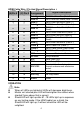
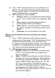

HDMI Ca
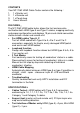
ble Wire / Pin And Signal Description:
HDMI
(A)Pin #
Mini-HDMI
(C) Pin #
Pin
Assignment
Signal Description
1 2 Data 2﹢ TMDS Red Data Plus (Data 2 +)
2 1 Data 2S TMDS Red Data Shield (Data 2 Shield)
3 3 Data 2﹣ TMDS Red Data Minus (Data 2 –)
4 5 Data 1﹢ TMDS Green Data Plus (Data 1 +)
5 4 Data 1S
TMDS Green Data Shield (Data 1
Shield)
6 6 Data 1﹣ TMDS Green Data Minus (Data 1 –)
7 8 Data 0﹢ TMDS Blue Data Plus (Data 0+)
8 7 Data 0S
TMDS Blue Data Shield (Data 0
Shield)
9 9 Data 0﹣ TMDS Blue Data Minus (Data 0 –)
10 11 Clock ﹢ TMDS Clock Plus (Clock +)
11 10 Clock S TMDS Clock Shield (Clock Shield)
12 12 Clock ﹣ TMDS Clock Minus (Clock –)
13 14 CEC Consumer Electronics Control
14 17 Uti./Res. Utility/Reserved
15 15 SCL Serial Clock (I2C)
16 16 SDA Serial Data (I2C)
17 13 DDC/CEC
Data shield for the display data
channel and consumer electronics
control
18 18 +5V Power + 5V Power
19 19 Hot Plug Hot Plug Detect
S S Shield Shield
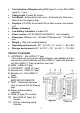
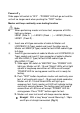
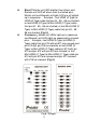
OPERATION
Note
When all LEDs are lighted all LEDs will decrease brightness.
Master unit shorted pins LED will be brighter than others when
shorted 2 pins above that is correct.
Shield LED will light up after #1~19 LEDs light up in sequence
on any testing mode. If the HDMI cable has a shield, the
Shield LED will light up, if without shield the LED will be
unlighted.
4