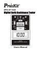
8PK-ST1520 Digital Earth Resistance Tester Users Manual
Page Index 1.INTRODUCTION ............................ 2.SAFETY NOTES............................. 3.FATURES........................................ 4.SPECIFICATIONS.............................. 5.LAYOUT........................................... 6.MEASURING METHODS................. 7.MAINTENANCE................................ 1 2 3 4 5 6-7 8 1.
●Purpose of Earth Grounding: (1)Avoid human and animal electrical shock. (2)Avoid unnecessary property and equipment damage. (3)Prevent fire or explosion. (4)Integrate electrical signal to attain proper operation or measuring purpose. (5)Provide a means of dissipation for power surges caused by lightning strikes, static charges, and other types of electrical interference. 2.SAFETY NOTES ●Read the following safety information carefully before attempting to operate or service the meter.
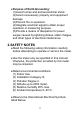
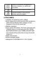
Meter is protected throughout by double insulation or reinforced insulation Warning! Risk of electric shock. Caution! Refer to this manual before using the Meter. 3.FEATURES ●Capable of measuring earth voltage. ●2mA measuring current permits earth resistance tests without tripping earth leakage current breakers in the circuit under test. ●Battery operated. ●Auto power off function.
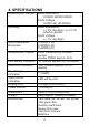
4. SPECIFICATIONS Measurement Ranges Accuracy Earth Resistance Resolution Measurement System Low Battery Indication Data Hold Indication Over Range Indication Open Circuit Indication Display LCD Power Source Dimensions Weight Accessories Earth Resistance 0-20Ω/0-200Ω/0-2000Ω Earth Voltage 0-200V AC (40-500Hz) Earth Resistance ± ( 2% rdg+2dgt ) or ± 0.1Ω. which is greater. Earth Voltage ± ( 1% rdg+2dgt ) 0-20Ω(0.01Ω) 0-200Ω(0.1Ω) 0-2000Ω(1Ω) Earth resistance by constant current inverter 820Hz approx. 2mA.
5.
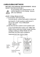
6.MEASURING METHODS BEFORE PROCEEDING MEASUREMENT, READ SAFETY NOTES ON PAGE 2. In proceeding with measurement, if "B" symbol appears on the display, replace with new batteries. ●Earth Voltage Measurement: (1) Connection with test leads: Connect green, yellow test leads to instrument terminals E, P with auxiliary earth bars P1, driven into earth " IN A STRAIGHT LINE".(Fig.
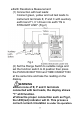
●Earth Resistance Measurement: (1) Connection with test leads: Connect green, yellow and red test leads to instrument terminals E, P and C with auxiliary earth bars P1, C1 driven into earth "IN A STRAIGHT LINE".(Fig.2) (2) Set the Range Switch to suitable range and set the function switch to Ω position then press the PUSH-ON BUTTON and TIME ON BUTTON at the same time and take the reading on the display.
7.MAINTENANCE ●Battery Replacement: When the symbol "B" appears on the display, replace the batteries as follows : (1) Disconnect the test leads from the instrument and turn off the power. (2) Use a screwdriver to unscrew the screw on back cover then slide the cover, take out the batteries and replace with new batteries Type SUM-3. (3) Place back cover and secure by a screw. ●Cleaning and storage: (1) Periodically wipe the case with a damp cloth and detergent ; do not use abrasives or solvents.