
User`s guide


www.projectiondesign.com
english
29
Geometry correction
Image Geometry Correction (often referred to as Image Warping) is the process of digitally
manipulating image data so that the image’s projection precisely matches a specifi c
projection surface or shape. Image Geometry Correction compensates for the distortion
created by off-axis projector or screen placement or non-fl at screen surfaces by applying a
compensating inverse distortion to the image in the digital domain. Usually, Image Geometry
Correction is applied so that areas of the projection surface are perceived by the viewer to
map to the corresponding areas in the source image.
Warping algorithms
The MIPS system is supporting 3 different warping algorithms: Perspective, Mesh Warp
Smythe, Mesh Warp Bezier. The best way to understand how they work is to test the
different algorithms in an actual system setup. One projector and one MIPS unit is enough to
learn how they work.
Note! Image Geometry Correction is not applied until operational mode is changed to
“online”.
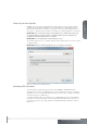
Perspective
This is advanced keystone. Only the four corners of the image can be manipulated.
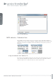
Mesh Warp Smythe
This is recommended for use on simple, maybe slightly curved screens. Number of control
points can be dynamically added. Start off with a few control points and increase the grid
size as needed. When the grid is increased, the position of any added point in the fi ner grid
mask will be given a correct position automatically. Max grid size is 16x16.
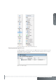
Mesh Warp Bezier
This is a very powerful tool where you can manipulate not only the control points of the grid,
but also the tangent vectors connected to every control point. The control points of the
tangent vectors are called Bezier control points.
Bezier patch meshes are superior to meshes of triangles as a representation of smooth
surfaces, since they are much more compact, easier to manipulate, and have much better
continuity properties. In addition, other common parametric surfaces such as spheres and
cylinders can be well approximated by relatively small numbers of cubic Bezier patches.
Max grid size is 16x16, but the fl exibility of this algorithm usually allows for correct geometric
distortion with very few control points.
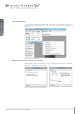
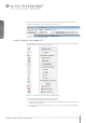
Warping user interface
To apply warping to an image, select “ Warp” from the left hand toolbar. The window in Figure
7-19 will appear.