INSTRUCTION BOOK FOR TENSIONED SCREEN
IMPORTANT SAFETY INSTRUCTIONS When using your video equipment, basic safety precautions should always be followed, including the following: 1. Read and understand all instructions before using. 2. Position the cord so that it will not be tripped over, pulled, or contact hot surfaces. 3. If an extension cord is necessary, a cord with a current rating at least equal to that of the appliance should be used. Cords rated for less amperage than the appliance may overheat. 4.
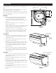
INSTALLATION Carefully unpack screen and remove outer wrapping from case. 5-11/16" Remove the retaining screws (through back of case) from the slat bar before the case is installed. There are three ways to install the tensioned screen: Wall Mount, Ceiling Mount, or Ceiling Hook. Procedures for each method are as follows: 2-5/16" 2-9/16" CASE HOOK Wall Mount 1. Secure the wall mount bracket to the wall at the desired height. Bracket should be fastened to wall studs or some reinforcement within the wall.
ELECTRICAL INSTALLATION Internal wiring has been completed at the factory. Installer must route power to the wall switch and to the junction box located on the left end of the screen case. Standard installation is for a single 120VAC or 240VAC wall switch to control the screen. Optional Control units may have been ordered. Wiring diagrams for the built-in VPI and low voltage control are included in these instructions.
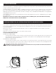
SCREEN ADJUSTMENT FOR 220/240V SCREENS WITHOUT BUILT-IN LOW VOLTAGE CONTROL Screen travel is stopped automatically in the down and up positions by the limit switches that are preset at the factory. If it's necessary to adjust for more or less drop follow the steps below. The case cover must be removed to access the motor limit switches. Remove the case cover screw from both ends of the screen. See figures 4 and 5. Be sure to hold the cover while removing the screws.
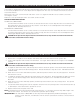
TENSIONED SCREEN INSTALLATION FIGURE 6 120V WIRING DIAGRAM FOR STANDARD WALL SWITCH JUNCTION BOX LOCATED IN LEFT ENDCAP JUNCTION BOX LOCATED IN LEFT ENDCAP WHITE BLACK RED GREEN BLUE BROWN BLACK GREEN MOTOR GROUND–MUST BE CONNECTED TO BUILDING GROUND BROWN AC (COMMON) OFF AC HOT 120VAC 60HZ 1 AMP RED THIS SWITCH CAN NOT BE USED WITH LVC. 2. BLUE AC COMMON BLACK NOTE: A SINGLE SWITCH CANNOT BE USED TO OPERATE MORE THAN ONE SCREEN. CONTACT THE FACTORY FOR FURTHER INFORMATION.
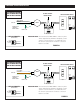
TENSIONED SCREEN INSTALLATION 120V WIRING DIAGRAM WITH OPTIONAL BUILT-IN LOW VOLTAGE CONTROL OPTIONAL IR AND RF REMOTE CONTROL LOW-VOLTAGE WALL SWITCH UP DN BLACK (HOT) 120VAC 60HZ GND +5V UP W H I T E (COMMON) MOTOR RJ22 RJ22 STOP GREEN DOWN 3-POSITION SWITCH RJ22 UP +5V COM DN GREEN GROUND–MUST BE CONNECTED TO BUILDING GROUND GROUND TO CASE FRONT BACK SPLITTER DRY CONTACTS ILT RJ22 PIN-OUTS IMPORTANT NOTE: The wall switch is REQUIRED to make any limit switch adjustments, EVEN if a t
TROUBLESHOOTING SYMPTOM 1. Screen will not operate. Motor does not hum. CAUSE SOLUTION (a) Incorrect line voltage. (a) Verify 115-125V (or 220-240V). If insufficient voltage, rewire incoming electric line. (b) Replace fuse. (c) Reset circuit breaker. (d) Check above. Tighten all loose wire connections. Correct any improper connections. “Down” Position Check for power across black and white leads. “Up” Position Check for power across red and white leads. (b) Blown fuse. (c) Tripped circuit breaker.