INTELLI-RV 12V POWER MANAGEMENT SYSTEM P/No.
IMPORTANT SAFETY INFORMATION Please read this manual thoroughly before use and store in a safe place for future reference. WARNINGS • Explosive gases. Prevent flames and sparks. Provide adequate ventilation during charging • Before charging, read the instructions • For indoor use. Do not expose to rain • For charging lead acid batteries ONLY (of the size & voltage specified in the specifications table) • Always charge the battery on the correct voltage setting.
CONTENTS 1. SYSTEM INTRODUCTION – PM200 ........................................................................................... 4 1.1 1.2 1.3 Features L.E.D Display Water tank probe 5 6 6 2. KEY FEATURES AND FUNCTIONS ............................................................................................... 7 2.1 2.2 2.3 2.4 2.5 2.6 2.7 2.8 2.9 2.
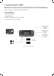
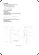
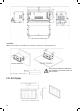
1. System Introduction – PM200 PM200 is designed for use in caravans or motor homes. The unit has integrated functions such as: battery charger, distribution blocks, PWM solar charger controller, charging relay, battery low voltage protector, water pump controller, water tank indicator and LED Display. The PM200 is designed for an easy installation and a user-friendly interface. SYSTEM COMPONENTS: 1. PM235 Master power unit 2. PMSWLED LED Display 3. PMWS200 or PMWS400 Water tank sensor (Not supplied) 4.
1.
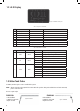
1.2 L.E.D Display Figure 3 PMSWLED switch panel Table 1 Front panel of PMSWLED NO LABEL TYPE DESCRIPTION 1 Water pump DC load control Load control, on/off control 2 Night mode Scene mode Refer to 2.10 3 Load DC load control Load control, on/off control. Refer to 2.
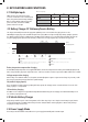
2. KEY FEATURES AND FUNCTIONS 2.1 Multiple Inputs Table 3 Source priority X X AC MAINS PM200 master power unit may have many sources at one time. These sources include the AC mains, solar panel and starter battery (Auxiliary). Only one of them will be dominated to provide power at one time, even if all are available, priorities are listed to the right. SOLAR AUXILIARY DOMINATING SOURCE AC MAINS X X X X AC MAINS AUX 2.
2.5 PWM Solar charger controller PM200 has a built-in PWM charger for the service battery. • Max input voltage 25VDC • Max charging current 20A • Max supply current 30A 2.6 Voltage Charging Relay (VCR or commonly known as a VSR) PM200 master power unit has a built-in voltage charging relay (VCR), which offers a convenient source to charge the service battery by alternator whilst engine is running. When the starter battery reaches 13.
3. STRUCTURE AND INSTALLATION 3.
Figure 9 Dimension of PM235 (unit: mm) Installation: PM235 can be installed on a horizontal surface or vertically on a wall. Please see following instructions: Ensure clearance on both sides of PM235 unit upon installation. A recommended clearance of 5cm on each side. Figure 10 Installation of PM235 (unit: mm) 3.2 L.E.
Installation Figure 12 Installation of PMSWLED (Unit: mm) 3.3 Water Tank Probe 3.3.1 PMWS400 Water Tank Probe Installation Figure 13 Dimension of PMWS400 (Unit: mm) Figure 14 Installation of PMWS400 3.3.
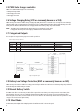
Solar 1 3 4 6 7 9 7 8 9 10 11 12 CODE PMSWLEDC P/NO. ON DRAWING PMBS Switch panel line Battery sensor line Water tank probe line Water tank probe line Water tank probe line Power Cable NAME PMWS200 / PMWS400 PMWS200 / PMWS400 5m 3m 4m 4m 4m 1.5m PMAC PMSWLEDC PMBS PMWS200 / PMWS400 P/NO. ON DRAWING PMWS200 / PMWS400 1 1 0 0 0 1 MODEL/LENGTH QTY 4.
4.3 Preparation PM200 system is designed with a concept of ‘Plug and Play’ in mind. To complete the easy installation, a screw driver and DC cables are required. Follow Table 7 recommendation for minimum wiring. CURRENT MINIMUM CABLE SIZE 0–5A 5–10A 10–15A 15–20A 20–25A 25–30A 1.0mm2 or 18 AWG 2.0mm2 or 14 AWG 3.0mm2 or 13 AWG 4.0mm2 or 11 AWG 5.0mm2 or 10 AWG 6.0mm2 or 9 AWG When running cables, if they pass through panels or wall, ensure the cables are protected from damage by sharp edges.
5. DISPLAY 5.1 PM235 Master Power Unit Figure 21 An overview of PM235 No.
5.2 L.E.D Display Figure 22 An overview of PMSWLED Table 10 Front panel of PMSWLED NO LABEL TYPE DESCRIPTION 1 Water pump DC load control Load control, on/off control 2 Night mode Scene mode Refer to 2.10 3 Load DC load control Load control, on/off control. Refer to 2.
6. OPERATION 6.1 Configuration on PM200 You could configure the battery type and capacity through PM235 master power unit. 6.1.1 Battery Capacity and Battery Type There is a dip switch for you to set battery capacity and battery type.
6.1.2 Select Battery Switch Local/Remote This function offers a possibility for user to use a remote battery switch to power on/off the service battery output Local DIP SWITCH DESCRIPTION Remote Local Remote The switch on PM235 unit works The remote switch works and local one is disabled Figure 24 Local/Remote Select Switch Table 16 Local/Remote Setting 6.2 Daily maintenance • Confirm the Battery Switch is switching on when you want to charge the battery with the AC grid.
7. TROUBLE SHOOTING 7.1 L.E.D Display on PM235 Unit No. LED COLOUR DESCRIPTION 1 Mains GREEN Quick flashing (flash twice every second) AC input abnormal 2 Str Bat GREEN Quick flashing (flash twice every second) The Starter Battery is 2~13.4V or >16.0V, while AC power is connected. 3 PV GREEN Quick flashing (flash twice every second) Solar input voltage error – Solar input >25Vdc 4 Fuse L.E.
8. SPECIFICATION MODEL PM235 ELECTRICAL SPECIFICATIONS Grid Battery PV Nominal input voltage (V) Power factor Input current at full load Starter Battery Starter battery voltage range Service battery Service battery voltage range Charger type Open circuit voltage Max supply current Max charging current Relay specification MODEL PM235 OTHERS 240±10%VAC 50/60Hz 0.95 2.5A Battery Disconnect (LVD) Disconnect voltage LiFePO4 Delay off time Reconnect voltage 12VDC 12.