
Manual


CONNECTING THE INVERTER
IP150
The IP150 is fitted with a lead and cigarette plug. Insert the plug into the vehicle’s
12V accessory socket and turn the inverter on. You may need to turn the vehicle’s
ignition to ‘accessory’ to supply power to the inverter.
IP300, IP600, IP1000
It is important to use suitable cable lengths and sizes to get the most out of your
inverter. Use of cable that is too thin or too long will result in voltage drop between
the battery and inverter, and may trigger low voltage warnings and inverter shutdowns.
It is recommended to place cable in corrugated conduit to protect from damage.
The following table lists suitable cable sizes for different cable lengths available
from Projecta.
Part Number (Description)
Cable Length 0–3m 3–6m
IP300 IWK1 (3m, 8mm
2
) IWK2 (6m, 26mm
2
)
IP600 IWK3 (3m, 32mm
2
) IWK4 (6m, 49mm
2
)
IP1000 IWK3 (3m, 32mm
2
) IWK5 (6m, 64mm
2
)
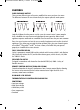
1. Prepare all cable ends with cable lugs.
2. Install a circuit breaker or high current fuse and fuse holder in the positive line as close
to the battery as possible. The following fuses are available from Projecta:
IP300: IFB-40 (40A fuse and holder)
IP600: IFB-100 (100A fuse and holder)
IP1000: IFB-150 (150A fuse and holder)
3. Make sure the inverter On/Off switch is turned OFF.
4. Connect the cables to the DC input terminals on the rear of the inverter.
The red terminal is positive (+) and the black terminal is negative (-).
a. Connect the positive cable to the inverter and battery positive terminals.
b. Connect the negative cable to the inverter and battery negative terminals.
5. The inverter is earthed through the negative DC input cable. Additional earthing can be
made by connecting an insulated wired from the chassis-ground terminal at the rear of
the inverter to the vehicle’s chassis or any other ground point.
FUSE
CORRUGATED CONDUIT
Intelli-Wave
6
IP150-1000 Instruction Manual_1 3/02/12 11:01 AM Page 6