
Installation Guide


6
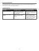
ASSEMBLY INSTRUCTIONS
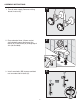
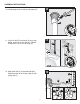
9. From below, insert ball rod (N) into drain
body (E).
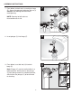
Note: Plunger (C) can be installed either in a
locked position, which prevents the plunger
(C) from being removed, or unlocked position,
which allows the plunger (C) to be removed
for cleaning.
8. Insert plunger (C) into fl ange (F).
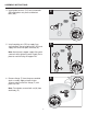
7. From below, reattach drain assembly to fl ange
(F). Secure into place by tightening lock nut (I).
Caution: Sink damage can occur from
overtightening.
NOTE: Opening for ball rod must
face toward rear of sink.
8
C
F
9
N
E
C
C
1
3
2
7
H
E
J
I
No
Yes
F
I
F