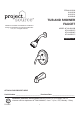
ITEM #1233229 #1233230 #1233231 #1328818 TUB AND SHOWER FAUCET PROJECT SOURCE and PROJECT SOURCE & Design are trademarks or registered trademarks of LF, LLC. All rights reserved. MODEL #F11A4503OB #F11A4503CP #F11A4503NP #F11A4503YP Español p. 19 ATTACH YOUR RECEIPT HERE Serial Number ____________________________ Purchase Date _________________________ Questions, problems, missing parts? Before returning to your retailer, call our customer service department at 1-866-389-8827, 8 a.m. - 8 p.m.
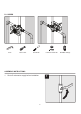
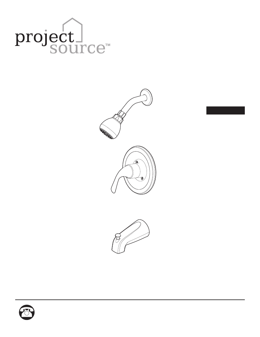
PACKAGE CONTENTS J C H B G A F E D I PART A B C D E F G H I J DESCRIPTION Shower head Shower arm Shower arm flange Handle Escutcheon Escutcheon seal Plaster guard Valve body Spout Plug 2 QUANTITY 1 1 1 1 1 1 1 1 1 1
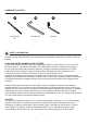
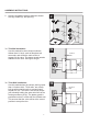
HARDWARE CONTENTS AA BB CC Long Screw x2 Hex Wrench Wrench SAFETY INFORMATION Please read and understand this entire manual before attempting to assemble, operate or install the product. NOISE AND WATER HAMMER IN PEX SYSTEMS As with all plumbing materials under some operating conditions, water hammer can occur in PEX plumbing systems. The inherent flexibility of PEX drastically reduces the magnitude of pressure surges compared with metallic plumbing materials.
SAFETY INFORMATION • This product is engineered to meet the EPA WaterSense flow requirement. The flow rate is governed by the aerator or flow controller. If replacement is ever required, be sure to replace it with a WaterSense compliant aerator or flow controller to retain the water conserving flow rate of this product. • The automatic compensating valve shall be used with shower rated at 1.3 gpm (4.9 L/min) or higher. • The shower shall be used with automatic compensating valve rated at 1.4 gpm (5.
B. PEX-1 B. PEX-2 B. PEX Use 1/2” Copper or IPS Pipe Only Use 1/2” Copper or IPS Pipe Only Tubing Cutter Full Circle Crimping Tool SharkBite Fittings SharkBite Fittings C. IPS-1 C. IPS Tubing Cutter Full Circle Crimping Tool C.
D. COPPER-1 D. COPPER-1 D. COPPER Torch Tube Cutter Torch Tube Cutter Lead-free Solder Kit Wire Brush SharkBite Fittings Wire Brush Lead-free Solder Kit ASSEMBLY INSTRUCTIONS 1 1. 1 Shut off main water supply before installation.
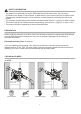
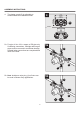
ASSEMBLY INSTRUCTIONS 2 2. 2 Note the installation distance between shower arm (B), handle (D), and spout (I). B 30 in. Shower Only 48 in. Tub & Sh ower D 48 in. Shower Only 8 in. M in. I 30 in. Tub & Sh ower 3a 3a. Thin Wall Installation: Use this method for when shower walls are thinner than 1/4 inch, such as fiberglass tub surrounds, and will be the main source of support for the valve. The plaster guard remains attached to the valve. See figure at right. 3a Less than 1/4” (6mm) 2-1/4” min.
4 ASSEMBLY INSTRUCTIONS The plaster guard (G) is adjustable to accommodate the installation needs. 4 5-1/2” (140 mm) 5-1/8 in. (130.3 mm) 2-3/4 in. (70.3mm) 4. G OPTION 3-1/16 in. (77.5 mm) 5a 5a. For pipe 4: Use 1/2 in. copper or IPS pipe only. If soldering connections, cartridge and integral stops must be removed to avoid heat damage. Reinstall when connections are completed and valve has cooled. 5a 3 1 2 4 5b 5b.
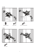
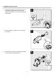
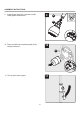
ASSEMBLY INSTRUCTIONS 6 6. 6 Install stub-out pipe (not included) for spout. Use proper length stub-out pipe so pipe threads will extend 1-1/2 to 2 inches beyond finished wall. 1 /2 11 ~2 in 2 7 7. Install tub spout (I). Tighten set screw using hex wrench. 7 1 I 2 8 8 8. Install shower arm (B) and shower arm flange (C) to vertical shower pipe elbow.
9 ASSEMBLY INSTRUCTIONS 9. Install shower head (A) to shower arm (B). Hand tighten shower head. 9 B 1 2 A 10 10 10. Remove plastic cap on plaster guard (G) by twisting clockwise. G 2 11 11 11. Turn on main water supply.
ASSEMBLY INSTRUCTIONS 12 12. Turn on water and check for leaks. 12 13 13. Remove valve cap. 13 2 1 14 14. Turn the valve counterclockwise to the full position. After several minutes, check the temperature using the thermometer. Slowly turn the valve clockwise to adjust the maximum water temperature to the desired temperature. CAUTION: The maximum water temperature should never be set above 120°F (49°C).
ASSEMBLY INSTRUCTIONS 15 15. Remove the red stop (a) and replace it against the stationary stop (c) to prevent the valve stem from turning further. Turn the lever to the off position once the temperature is set. NOTE: Do not move the blue stop (b). Seasonal maintenance of the maximum outlet temperature may be required due to changes in groundwater temperature. 15 red stop a red stop a 1 b blue stop a c 2 b blue stop a c b b 16 16. Replace valve cap. a c b 16 1 2 17 17.
ASSEMBLY INSTRUCTIONS 18 18. Install handle (D) with screw and insert handle cap.
BACK TO BACK INSTALLATION 1. Remove valve cap. 1 2 2. Remove red stop (a) and blue stop (b) and rotate valve 180°. 1 2 a b 180° 2 1 c a b 3. Replace red stop (a) and blue stop (b). Replace valve cap.
CLEANING SCREEN WASHER 1 2 B AA 2 1 A 1. Use a clean strap wrench (not included) to remove the shower head (A) from shower arm (B). 2. Use a flathead screwdriver (not included) to carefully remove the screen washer. 4 2 3 A AA 3. Gently clean the screen washer with a toothbrush (not included). 1 4. Reinstall the screen washer and shower head (A). Hand tighten shower head. CARE AND MAINTENANCE • To protect and maintain the finish of your faucet, clean only with a soft, damp cloth.
TROUBLESHOOTING PROBLEM Hot and cold are reversed. POSSIBLE CAUSE Lines reversed or cartridge installed upside down. There is no or a low water flow. One or both water supplies are not turned on. There is leaking or dripping Grommets not sealing properly. from the spout. Misplacement of temperature limit stops. There is only hot water or only cold water from the spouts. Water comes out of the tub spout and showerhead at the same time. Balancing spool stuck.
REPLACEMENT PARTS LIST For replacement parts, call our customer service department at 1-866-389-8827, 8 a.m. - 8 p.m., EST, Monday - Friday. 11. 12. 13. 10. 14. 9. 8. 7. 6. 5. 1. 15. 3. 4. 2.
ARTÍCULO #1233229 #1233230 #1233231 #1328818 GRIFO PARA BAÑERA Y DUCHA PROJECT SOURCE y PROJECT SOURCE & Design son marcas o marcas registradas de LF, LLC. Todos los derechos reservados. MODELO #F11A4503OB #F11A4503CP #F11A4503NP #F11A4503YP ADJUNTE SU RECIBO AQUÍ Número de serie Fecha de compra ¿Preguntas, problemas, piezas faltantes? Antes de volver a la tienda, llame a nuestro Departamento de Servicio al Cliente al 1-866-389-8827, de lunes a viernes de 8 a.m. a 8 p.m., hora estándar del Este.
CONTENIDO DEL PAQUETE J C H B G A F E D I PIEZA A B C D E F G H I J DESCRIPCIÓN Cabezal de ducha Brazo de ducha Brida del brazo de ducha Manija (preensamblada) Escudo de bocallave Sello del escudo de bocallave Protector de yeso Cuerpo de la válvula Boquilla Conector 20 CANTIDAD 1 1 1 1 1 1 1 1 1 1
ADITAMENTOS AA BB Tornillo largo x2 Llave hexagonal CC Llave INFORMACIÓN DE SEGURIDAD Lea y comprenda completamente este manual antes de intentar ensamblar, usar o instalar el producto. RUIDO Y GOLPES DE ARIETE EN LOS SISTEMAS PEX Como en todos los materiales de plomería que están bajo ciertas condiciones de funcionamiento, en los sistemas de plomería PLEX también pueden ocurrir golpes de arriete.
INFORMACIÓN DE SEGURIDAD • Este producto se diseñó para cumplir los requisitos de flujo Watersense de la EPA. El índice de flujo está regulado por el aireador o por el caudal de flujo. Si alguna vez se requiere reemplazo, asegúrese de reemplazarlo con el aireador de flujo o con el aireador que cumpla con la norma WaterSense para mantener el índice de flujo que conserva el agua de este producto. • La válvula automática de compensación se debe utilizar con una ducha calificada a 4,9 l/m (1,3 gpm) o más.
B. PEX-1 B. PEX-2 B. PEX Use únicamente tuberías de cobre de ½”o IPS Use únicamente tuberías de cobre de ½”o IPS Tubing Cutter Full Circle Crimping Tool SharkBite Fittings Conectores SharkBite C. IPS-1 C. IPS Cortador de tuberías Herramienta de engarzado de círculo completo C.
D. COPPER-1 D. COPPER-1 D. COBRE Torch Soplete Cortador de tubos Lead-free Solder Kit Wire Brush Tube Cutter SharkBite Fittings Cepillo de alambre Kit de soldadura sin Conectores SharkBite plomo INSTRUCCIONES DE ENSAMBLAJE 1 1. Cierre el suministro principal de agua antes de la instalación.
INSTRUCCIONES DE ENSAMBLAJE 2 2. Tenga presente la distancia de instalación entre el brazo de la ducha (B), la manija (D) y la boquilla (I). 2 B 76.2 cm Ducha so lamente 1.22m Bañera y ducha D 20.3 cm 1.22 Ducha so m lamente mín. I 76.2 cm Bañera y ducha 3a 3a. Instalación delgada en la pared Para paredes de menos de ¼ pulgada.
4 INSTRUCCIONES DE ENSAMBLAJE 4. El protector de yeso (G) es ajustable para acomodar las necesidades de instalación. 4 2 3/4 pulg. (69.85mm) 5 3/8 pulg. (136.52mm) 5 1/8 pulg. (130.17mm) G OPCIÓN 3 1/16 pulg. (77.78mm) 5a 5a. Para la tubería 4: Use únicamente tuberías de cobre de ½”o IPS. Si las conexiones de soldado, el cartucho y los topes integrales deben retirarse para evitar el daño ocasionado por calor y se deben reinstalar cuando la conexión se haya completado y la válvula se haya enfriado.
INSTRUCCIONES DE ENSAMBLAJE 6 6. Instale la tubería saliente (no se incluye) para la boquilla. Use una tubería saliente de de un largo adecuado para que las roscas de la tubería se extiendan de 3,81 cm a 5,08 cm más allá de la pared acabada. 6 1 1a 3,8 8 cm 2 5,0 7 7. Instale la boquilla de la bañera (I). Apriete el tornillo de fijación con la llave hexagonal. 7 1 I 2 8 8. Instale el brazo de la ducha (B) y la brida (C) del brazo de la ducha en el codo de la tubería vertical de la ducha.
9 INSTRUCCIONES DE ENSAMBLAJE 9. Instale el cabezal de ducha (A) en el brazo de la ducha (B). Apriete manualmente el ca bezal de ducha. 9 B 1 2 A 10 10. Retire la tapa de plástico del protector de yeso (G) girándola en dirección de las manecillas del reloj. 10 G 2 11 11. Abra el suministro principal de agua.
INSTRUCCIONES DE ENSAMBLAJE 12 12. Abra el suministro de agua y revise que no haya fugas. 12 13 13 13. Retire la tapa de la válvula. 2 1 14 14. Gire la válvula en dirección contraria a las manecillas del reloj hacia la posición completamente. Después de varios minutos, verifique la temperatura con el termómetro. Lentamente, gire la válvula en dirección de las manecillas del reloj para regular la temperatura máxima del agua a la temperatura deseada.
15 INSTRUCCIONES DE ENSAMBLAJE 15 tope rojo a tope rojo a b tope azul a c 2 b tope azul 1 15. Retire el tope rojo (a) y reemplácelo apoyado en el tope fijo (c), así evitará que el vástago de la válvula gire más allá de lo deseado. Gire la palanca a la posición de apagado cuando la temperatura esté fija. NOTA: No mueva el tope azul (b). Es posible que se requiera un mantenimiento por temporada de la temperatura de salida máxima debido a los cambios en la temperatura del agua del subsuelo.
INSTRUCCIONES DE ENSAMBLAJE 18 18. Instale la manija (D) con tornillos e instale la tapa de la manija.
INSTALACIÓN DE PARTE POSTERIOR CONTRA PARTE POSTERIOR 1. Retire la tapa de la válvula. 1 2 2. Retire el tope rojo (a) y el tope azul (b) y gire la válvula a 180°. 1 2 a b 180° 2 1 c a b 3. Reemplace el tope rojo (a) y el tope azul (b). Vuelva a colocar la tapa de la válvula.
LIMPIEZA DE LA ARANDELA DE LA MALLA 1 2 B AA 1. 2 1 A Use una llave de correa (no se incluye) limpia para retirar el cabezal de ducha (A) del brazo de la du-cha (B). 2. 3 Use un destornillador de cabeza plana (no se incluye) para retirar con cuidado la aran-dela con filtro (F). 2 4 A 1 3. Limpie con cuidado la arandela con filtro (F) con un cepillo de dientes (no se incluye). 4. Vuelva a colocar la arandela con filtro y el cabezal de ducha (A). Apriete manualmente el ca bezal de ducha.
SOLUCIÓN DE PROBLEMAS PROBLEMA Caliente y frío están invertidos. CAUSA POSIBLE Las líneas están invertidas o el cartucho está instalado en posición invertida. ACCIÓN CORRECTIVA Gire el vástago del cartucho 180°, de modo que la muesca mire hacia abajo y hacia el desagüe. No hay flujo de agua o hay un flujo de agua bajo. Uno o ambos suministros de agua no están encendidos. Gire ambas válvulas de suministro de agua en dirección contraria a las manecillas del reloj a la posición de encendido.
GARANTÍA El fabricante garantiza que este grifo no presentará defectos en la mano de obra ni en los materiales presentes en el momento del transporte desde la fábrica durante un período limitado de por vida a partir de la fecha de compra. Esta garantía es válida sólo para el comprador original. El fabricante acepta reparar dichos defectos sin cargo o, según nuestro criterio, reemplazar el grifo por un modelo comparable o superior.
LISTA DE PIEZAS DE REPUESTO Para obtener piezas de repuesto, llame a nuestro Departamento de Servicio al Cliente al 1-866-389-8827, de lunes a viernes de 8 a.m. a 8 p.m., hora estándar del Este. 11. 12. 13. 10. 14. 9. 8. 7. 6. 5. 1. 15. 3. 4. 2. PIEZA 1 2 3 4 5 6 7 8 9 10 11 12 13 14 15 DESCRIPCIÓN Manija de metal Tapa de la manija Tornillo (W3/16 pulg. -24 * 3 9/16 pulg. de largo) Ensamble del escudo de bocallave Juego de tornillos (3/16 pulg. -24 * 2-3/16 pulg.