
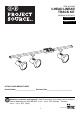
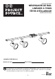
Installation Guide


7
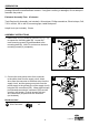
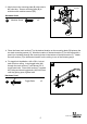
7. Insert a 50-watt max., 120-volt R/PAR20-base
bulb (not included) into the track head (G).
8. Identify ground side on the track head (G) connector
and track section (F).
Push the top portion of the track head (G) connector
into the slot of the track section (F). Pull down the
connector’s locking tab. Twist ground side of the
track head (G) connector toward the ground side
the track section (F) until the track head (G)
connector snaps into place.
NOTE: The ground side of the track head (G)
connector is the side with two metal tabs. The
ground side of the track section (F) has an indented
groove on the face and two internal copper strips.
The track head (G) can only be assembled if the
ground sides of the track head (G) connector and
the track section (F) are aligned.
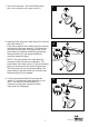
9. To remove the track head (G) from the track
section (F), first allow the track head (G) to cool
down. Pull down on the track head (G)
connector’s locking tab, and twist until the
track head (G) disengages.
7
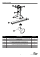
G
F
GROUND
TAB
GROUND GROOVE
GROUND SIDE OF
CONNECTOR
8
G
F
9
G
F
Lowes.com