ITEM #0806942 0806941 LED FLUSHMOUNT CEILING FIXTURES Project Source® is a registered trademark of LF, LLC. All Rights Reserved. MODEL #CLL11-2BNK CLL11-2WW Français p. 9 Español p. 17 ATTACH YOUR RECEIPT HERE E479007 Purchase Date Questions, problems, missing parts? Before returning to your retailer, call our customer service department at 1-866-389-8827, 8 a.m. - 6 p.m., EST, Monday - Thursday, 8 a.m. 5 p.m., EST, Friday.
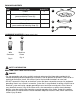
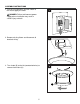
PACKAGE CONTENTS PART DESCRIPTION QUANTITY A Fixture 2 B Shade (preassembled to Fixture (A)) 2 C Mounting Strap A 2 B D Fixture Screw (preassembled to Mounting Strap (C)) 4 C D HARDWARE CONTENTS (shown actual size) AA BB Wire Connector Machine Screw Qty. 6 Qty. 4 SAFETY INFORMATION READ AND SAVE THESE INSTRUCTIONS.
SAFETY INFORMATION • DO NOT connect the bare or green insulation fixture ground wire to the black (HOT) current-carrying wire or the white (NEUTRAL) house wire. Connection of the bare or green fixture ground wire to the black or white house wires may cause metal parts of the fixture to carry electrical currents. Under this condition, anyone coming in contact with the fixture will receive electrical shock, which could cause serious injury or death.
SAFETY INFORMATION CAUTION • TURN OFF ELECTRICITY at main fuse box (or circuit breaker box) before beginning installation by removing the fuse (or switching the circuit breaker off). • If you are not sure the lighting system has a grounding means, DO NOT attempt to install this fixture. Contact a qualified, licensed electrician for information regarding the proper grounding methods as required by the local electrical code in your area.
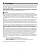
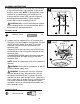
ASSEMBLY INSTRUCTIONS 1. Turn off circuit breakers and wall switch to the fixture supply line leads. 1 DANGER: Failure to disconnect power supply prior to installation may result in serious injury or death. 2. Remove existing fixture and disconnect all electrical wiring. ON ON OFF OFF 2 Outlet Box 3. Turn shade (B) to the left (counterclockwise) to remove from fixture (A).
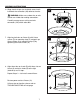
ASSEMBLY INSTRUCTIONS 4. Attach mounting strap (C) to outlet box (not included) using existing washers and outlet box screws or the machine screws (BB). NOTE: If the outlet box screws required for your outlet box are of a different size than the machine screws (BB), consult a licensed electrician before proceeding. Tighten machine screws (BB) to secure mounting strap (C). 4 CAUTION: Make sure the outlet box can support 35 lbs. hanging weight. Use metal outlet box; plastic outlet boxes are not recommended.
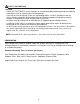
ASSEMBLY INSTRUCTIONS 6. Wrap electrical tape (not included) around each individual wire connector (AA) down to the wire. 6 Outlet Box AA WARNING: Make sure no bare wire or wire strands are visible after making connections. AA Carefully arrange excess wiring and wire connectors (AA) within outlet box. AA 7. Align keyslot holes on fixture (A) with fixture screws (D) on mounting strap (C) and push up. Secure fixture (A) to mounting strap (C) by tightening the fixture screws (D). 7 D A 8.
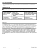
CARE AND MAINTENANCE • Shut off main power supply. Wipe with soft cloth or use window cleaner. Do not use an abrasive cleaner. TROUBLESHOOTING WARNING: Before beginning work, shut off the power supply to avoid electrical shock. PROBLEM POSSIBLE CAUSE CORRECTIVE ACTION Light does not come on initially or no longer comes on. 1. Power is OFF. 2. Faulty connection. 3. LED component is not working properly. 1. Make sure power supply is ON. 2. Check wiring and all connections. 3. Contact Customer Service.