
Installation Guide


BACKBOX INSTALLATION
93034795
Enclosure:
Trim Ring:
Trim Ring Screws:
Hanger Bars:
Hanger Bar Screws:
T-Bar Clips:
T-Bar Screws:
1
1
4
4
2
4
4
Enclosure:
Trim Ring:
Trim Ring Screws:
Hanger Bars:
Hanger Bar Screws:
T-Bar Clips:
T-Bar Screws:
1
1
4
4
2
0
0
Enclosure:
Trim Ring:
Trim Ring Screws:
Hanger Bars:
Hanger Bar Screws:
T-Bar Clips:
T-Bar Screws:
1
1
4
4
4
0
0
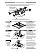
Use template provided to cut
hole in ceiling tile. (Note the
range of hanger bars - template
should be centered along
h
anger bar direction.) Knock out
the most convenient knock-out in the
enclosure and thread wiring through,
and install conduit fitting and conduit.
Mount hanger bars with clips to the
T-Grid. Slide the trim ring down
to level of tile face and tighten
trim ring screws.
T-Grid Ceiling:
Between Joists:
Between Joists
Turned 90
°:
93067925
93067918
93067919
93067920
T-BAR CLIP (4) AND SCREW (4)
HANGER BAR (4)
TRIM RING
TRIM RING SCREW (4)
HANGER BAR SCREW
* 2 IF SIDE MOUNTED *
* 4 IF END MOUNTED *
ENCLOSURE
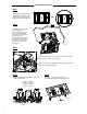
Use template provided to cut
hole in ceiling. (Note the
range of hanger bars - template
should be centered along
hanger bar direction.) Knock out
the most convenient knock-out in the
enclosure and thread wiring through,
and install conduit fitting and conduit.
Hammer hanger bars into joists and
secure with one nail through one hole
in each hanger bar . Slide the trim
ring flush with theceiling face and
tighten
trim ring screws.
Remove the hanger bar screws on
the sides of the enclosure and slide
the hanger bars out of the tabs.
Secure each pair of hanger bars on
the ends of the enclosure with 2
screws, making sure both screws pass
through the slots in both hanger bars.
(The distance this hanger bar
orientation will reach is limited to
21 inch joist spacing. Add spacers
to joists if necessary.) Now follow
"Between Joists" inst
ructions.
Note - in this orientation, only the top
enclosure knock-out can be used.
Once hammered in,
add nail to each tab here
Once hammered in,
add nail to each tab here
BACKBOX INSTALLATION
This unit is designed to be mounted in the ceiling. Provide standard unit with a single unswitched supply from a
120-277VAC, 50/60Hz branch circuit used for normal lighting in area to be protected. For
self-testing/self-diagnostic unit, provide unit with a 120VAC or 277VAC 50/60Hz branch circuit.
The rectangular light pattern emitted from the PECEM
is oriented the same as the rectangular enclosure.
Cho
ose from below the corresponding mounting method accordingly:
2