GULLIVER Ceiling Fan Installation Manual
Limited Lifetime Warranty Progress Lighting fan motors are warranted to the original purchaser to be free of electrical and/or mechanical defects for so long as the original purchaser owns the fan. Pull chain switches, reverse switches, capacitors and metal finishes are warranted to be free from defects in materials or workmanship for a period of 1 year from the date of purchase.
Safety Rules............................................................................................................................................ Unpacking Your Fan ............................................................................................................................... Installing Your Fan ................................................................................................................................. Operating Your Transmitter ..................................
1. To reduce the risk of electric shock, insure electricity has been turned off at the circuit breaker or fuse box before beginning. 8. To avoid personal injury or damage cautious when working around or clea 2. All wiring must be in accordance with the National Electrical Code and local electrical codes. Electrical installation should be performed by a qualified licensed electrician. 9. Do not use water or detergents when dry dust cloth or lightly dampened cleaning. 3.
ON DIP 1 2 3 4 1 5 3 2 MED HI LOW OFF 6 4 7 Unpack your fan and check the contents. You should have the following items: 1. Canopy assembly 2. Ball/downrod assembly 3. Fixture assembly 4. LED bulbs (3) 5. Receiver 6. Transmitter 7. 9V battery 8. Loose par a. Mounting b. #8 X 1-1/ c. #8-32 Scr d. Flat wash e. Spring wa f.
Tools Required Angled ceiling maximum 18.5 angle Phillips screw driver, straight slot screw driver, adjustable wrench, step ladder, and wire cutters. Mounting Options Recessed outlet box If there isn't an existing cUL listed mounting box, then read the following instructions. Disconnect the power by removing fuses or turning off circuit breakers. Secure the outlet box directly to the building structure. Use appropriate fasteners and building materials.
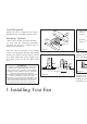
Hanging the Fan REMEMBER to turn off the power. Follow the steps below to hang your fan properly: Step 1. Insert the end of downrod (B) through the connector (PP),align the two holes in the downrod (B) and the connector (PP).(Fig.5) Step 2. Insert a plug pin (GG) through the two holes in the downrod (B) and the connector (PP). (Fig.5) Step 3. Insert the R-shaped pin (HH) though the hole near the end of the plug pin (GG) until it snaps into its locked position. (Fig.5) Step 4.
Make the Electric Connections WARNING: To avoid possible electrical shock, be sure electricity is turned off at the main fuse box before wiring. CODE SWITCH: Codes are set by pushing dip switches up or down. It is imperative that the code used for both transmitter and receiver is exactly the same, otherwise remote controller will not work. Please note the code switch will enable you to operate a second remote controller independently.
5. Installing met Step 4. Once the connection has been made, the receiver inserts into the drop rod hanging bracket. The canopy comes up to cover the receiver and bracket. (Fig. 10) Step 1. Insert the f shaft (U), install lo after the blade ass 12) Step 2. Screw ligh sockets. (Fig. 12) Step 3. Align the l grill (G) with thre fixture (E). Push u lock in place. (Fig Installing the canopy: Step 1. Align the locking slots of the canopy (C) with the two screws (FF) in the mounting bracket (A).
6.
The Reverse s housing. Slide t weather operatio for cool weather FUNCTIONS OF TRANSMITTER: OFF HI : Turn off the ceiling fan. NOTE: Wait for f of the slide switch : Turn on the fan at high speed. MED : Turn on the fan at medium speed. LOW : Turn on the fan at low speed. LIGHT : ON/OFF- Press and release immediately to turn on or off the light. Speed settings fo factors such as the fans, etc. Installation of Transmitter Wall Mount Holder with two screws.
Disassembling Your Fan This fan comes with a pre-assembled the blade and front guard for your easy installation. Check that all screws are tight and securely in place. Use a lint free lightly damp cloth or duster to remove dust from the blades.
Here are some suggestions to help you maintain your 3. You can apply a light coat of furniture polish to the fan wood blades for additional protection and enhanced beauty. Cover small scratches with a light application 1. Because of the fan's natural movement, some of shoe polish. connections may become loose. Check the support connections, brackets, and blade attachments 4. There is no need to oil your fan. The motor has twice a year. Make sure they are secure. (It is not permanently lubricated bearings.
Problem Solution Fan will not start. 1. Check circuit fuses or breakers. 2. Check line wire connections to the fan and switch wire connections in the switch housing. CAUTION: Make sure main power is off. 3. Check to make sure the dip switches from the transmitter and receiver are set to the same frequen Fan sounds noisy. 1. Make sure all motor housing screws are snug. 2. Make sure the screws that attach the fan blade bracket to the motor hub is tight. 3.
Size Speed Volts Low 14in. Medium 120 High Fan Power Consumption (without lights) WATT Airflow CFM Airflow Efficiency (Higher Is Better) CFM/WATT 22.93 873.41 XXX XX XXXX XXX 39.05 1297.28 32.99 Net Weight Gross Weight 24.8 lb (11.27kg) 28.76 lb (13.06kg) These are approximate measures. They do not include Amps and Wattage used by the light kit. c 2018 Progress Lighting, Inc. 701 Millennium Blvd., Greenville, SC 29607 All Rights Reserved 11.