PRORAD Series X-Ray Flat Panel Detector Operation Manual Prognosys Medical Systems Private Limited 1 © Prognosys Medical Systems Private Limited│ X-Ray Products
Radiologist or any other practitioners licensed should ensure that they have adequate knowledge of the operation prior using the PRORAD X-Ray Flat Panel Detector. This Operation Manual should be studied and understood before proceeding to operate the equipment on patients; it describes details on how to operate the PRORAD X-Ray Flat Panel Detector and cautions to be observed when operating it.
Table of Content Chapter 1 Introduction .......................................................................................................................... 6 1.1 Product Introduction........................................................................................................... 7 1.2 Product Series ..................................................................................................................... 7 1.3 Product Intended Use .................................................
2.17.6 PRORAD CS Label ..................................................................................................... 34 2.17.7 Charger Label ............................................................................................................ 34 2.17.8 Charger SN Label ...................................................................................................... 34 2.17.9 Adapter Specification Label (Charger) ..................................................................... 35 2.
A.1.3 Power Supply to Battery Charger .............................................................................. 75 A.1.4 Power Consumption and Battery Specification ........................................................ 75 A.1.5 Environmental Conditions ......................................................................................... 75 A.1.6 Image Performance.................................................................................................... 77 A.1.7 Radio Waves .............
Chapter 1 Introduction This manual is intended to provide the operator with an overview of the operation and safety requirements for the PRORAD X-Ray Flat Panel Detector. This manual is not intended to provide instructions on actual treatment procedures and it is expected that users should have official radiologist or any other practitioners license prior to using the device. The Manufacturer and Distribution organization assume no liability through the use of the device.
product such as power supply, installation environment, etc. contained in this manual. Prognosys Medical Systems Private Limited. shall not be liable for malfunctions and damages resulting from natural disasters such as fires, earthquakes, floods, lightning, etc. _________________________________________________________________________________ 1.1 Product Introduction PRORAD X-Ray Flat Panel Detector is an X-ray image acquisition device that is based on flat-panel.
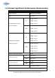
1.4 Product Significant Performance Characteristics Items Characteristics Image resolution 2500x3052 / 3072x3072 Data 16 bit data 0.69 @ 1 lp/mm CsI 0.39 @ 2 lp/mm MTF (Modulation transfer 0.22 @ 3 lp/mm function) (Typical) 0.52 @ 1 lp/mm GOS 0.23 @ 2 lp/mm 0.11 @ 3 lp/mm 0.51 @ 0.5 lp/mm 0.48 @ 1 lp/mm CsI 0.39 @ 2 lp/mm DQE (Detector quantum 0.29 @ 3 lp/mm efficiency) (Typical) 0.31 @ 0.5 lp/mm 0.27 @ 1 lp/mm GOS 0.16 @ 2 lp/mm 0.
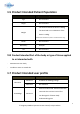
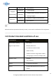
1.5 Product Intended Patient Population Considerations Requirement Description Age - Not restricted Height - Not restricted - The uniform load of the device is 300kg - The local load on 4 cm diameter of the Weight device is 120kg. *Note: Please evaluate the patient’s condition before using. Health - Not restricted Nationality - Multiple Sex - Not restricted 1.
Maximum - No maximum Minimum - Local language - Understand the operation manual that is Language Understanding Maximum writing in English Minimum - Physician or legally certified operator Maximum - No maximum Experience _________________________________________________________________________________ Note Patient should not operate the device by its own, in case result in malfunction of the equipment. _________________________________________________________________________________ 1.
1.9 Product Features - 140 micron pixel pitch - Wide image - 16-bit dynamic range output - Exposure times up to 3.0 seconds - Wireless communication mode or wired communication mode is available. When used in wireless communication mode, an access point and battery pack (optional) are required. 1.10 Clinical Guide Users may require to attend the training courses held by Prognosys before using.
Chapter 2 Safety and Regulatory This PRORAD X-Ray Flat Panel Detector has been designed and tested to function in a safe and correct when used as indicated in this manual. Do not use this device before reading and completely understand this Operation Manual. Always observe precautions for safety and only operates the device in a qualified room that provides protection. 2.1 Compliance Standards and Classification 2.1.1 Compliance Standards - FDA Standards 21 CFR 1020.
- EN 1041:2008 - EN ISO 15223-1:2016 - RED Directive (2014/53/EU) - RoHS Directive (2011/65/EU) 2.1.2 Classification - Type of protection against electrical shock: Class I Equipment - Degree of protection against electrical shock: Type B Equipment - Degree of protection against harmful ingress of water: IPX6 (An IPX6 rating does not indicate compliance with, and the detectors have not been tested for compliance with, any other IPX_ ratings.
- Install the equipment in a location where it will not be exposed to water. - Check that the equipment is securely earthed. - Check that all of the cables are completely and securely connected. - Keep the control cabinet out of reach of patients. Cautions Do not reverse conneting positive and negative power terminal, it might cause short circuit and patient/user will be harmed. _________________________________________________________________________________ 2.
otherwise it may result in electric shock or malfunction of the equipment. - Do not attract any metal conductive objects to avoid short circuit, make sure the back-up cable is clean Do not use the equipment in a location where metal particles could come into the equipment. This may cause an electric shock. Do not disassemble or remodel the equipment. Otherwise, fire or electric shock may result. Keep away from the parts inside the product, which may cause electric shock.
Keep the equipment away from patient’s body fluids, chemicals, water, etc. Otherwise, it may be damaged, causing fire or electric shock. If necessary, protect the flat panel detector by covering it with a disposable bag. _________________________________________________________________________________ 2.
- Where the equipment is subject to frequent or excessive vibration/shock. - Where the equipment is exposed to direct sunlight. Use the equipment on a flat place. If the equipment falls, it may cause damage to the equipment or personal injury. When you move the equipment, place it in the cassette storage box of a mobile X-ray unit or hold it by hand to prevent it from falling. If the cart is used to move the equipment, place it horizontally.
_________________________________________________________________________________ 2.7 Connection Instructions _________________________________________________________________________________ Warning Make sure that the devices to be connected to the equipment are authorized for connection. Connect the panel unit PRORAD only to the access point or DR system. _________________________________________________________________________________ 2.
Warning Make sure to use the optional parts, accessories and networks recommended by us. Failure to use the optional parts, accessories and networks recommended by us may result in damage to the equipment and/or electric shock and injury. Connect to the Ethernet Network of 100BASE-TX or 10BASE-T prescribed in the IEEE standard 802.3. Do not connect telephone lines to LAN connector.
_________________________________________________________________________________ 2.10 Software Precautions _________________________________________________________________________________ Caution Do not install additional software to the system. Do not uninstall any of the software preinstalled in the system. The system is preinstalled with the appropriate software. If other software is installed or if the existing software is uninstalled, various operational errors may result.
- Chloric disinfectant which is strongly corrosive to metals and rubber parts. - Disinfectant whose uses on metals, plastics, and coating are forbidden according to the instructions supplied with the disinfectant. - Formalin gas and disinfectant sprays that may get inside the equipment. - Ultraviolet sterilizers. Disinfectant ethanol is recommended for disinfection. Carefully read the instructions and cautions supplied with the disinfectant before use.
Do not charge the battery pack near fire or under strong sunshine. If the built-in protection mechanisms are activated by a high temperature, the battery pack cannot be charged. Also, if the built-in protection mechanisms are damaged, the battery pack may be charged with extremely high current and voltage, and abnormal chemical reactions may occur inside the battery pack, causing it to overheat, emit smoke, explode or ignite.
If this equipment is not in use for while, store it with the battery pack removed. Not removing the battery pack may cause malfunction. Caution The battery pack is used with the flat panel detector. Do not use them in other combinations. Charge the battery pack only with the designated battery charger. If the battery pack is charged under the charging conditions (voltage, current and charging method) different from those specified by Prognosys Medical Systems Private Limited.
Do not connect the positive (+) and negative (-) terminals with a wire or any metal object. Do not carry or store the battery pack together with metal objects such as necklaces or hairpins. Otherwise, the battery pack may short-circuit and overcurrent may flow, causing the battery pack to overheat, emit smoke, explode or ignite. Metal objects such as necklaces or hairpins may also become hot. Do not throw the battery pack into fire or expose it to excessive heat.
Do not solder the battery pack directly. Otherwise, its insulator may melt, or its gas release vent or safety mechanisms may be damaged, causing the battery pack to overheat, emit smoke, explode or ignite. Do not reverse the positive (+) and negative (-) terminals. Otherwise, the battery pack may be reverse-charged during charging.
battery of a different capacity, type and/or brand. Otherwise, the battery pack may be overcharged during charging, and abnormal chemical reactions may occur inside the battery pack, causing it to overheat, emit smoke, explode or ignite. Do not put the battery pack in a microwave oven or high-pressure container. Otherwise, the battery pack may be rapidly heated or damaged, causing it to overheat, emit smoke, explode or ignite.
Regarding the storage of the battery, first of all, the best storage capacity of the battery is about 40~50%. Before the installation, when the battery and the product are still in the warehouse, it is recommended that the main battery and the internal battery must be checked every 3 months to charge. The main battery needs to be charged to 50%, two bars of the charging stand, and it takes about 2 hours to charge from 0%.
radiation necessary to obtain appropriate medical images. For system operation, if children can not use the AEC. Adjust the exposure conditions to minimize the X exposure due to body movement. _________________________________________________________________________________ 2.15 Other Precautions _________________________________________________________________________________ Warning No modification of this equipment is allowed.
Although the flat panel detector conforms to IPX6, no warranty is given as to the prevention of water intrusion in the flat panel detector. If the flat panel detector is splashed with water, wipe off moisture and ensure that the flat panel detector is completely dry before use. As the cables of the equipment are long, be careful not to entangle the cables during use. Also, be careful not to trip over the cables. Falls could result in injury. Follow the specified procedure when turning off the equipment.
by heat. Do not take image while FPD is in busy state, patient might need to retake. Make sure use the right FPD when mutiple FPD are standby in the same time, use wrong FPD will result in patient retake. The orange light is on, not only means that there is a problem with the FPD, but it may also mean that the internal image storage space is full. Please use the INCX Service tool to clear the image in the memory before continuing to use it.
2.17.
PRORAD V17 Clarity PRORAD V17 HC 2.17.
2.17.3 Battery Label 2.17.
2.17.5 Adapter Specification Label 2.17.6 PRORAD CS Label 2.17.7 Charger Label 2.17.
2.17.
2.17.10 Safety Symbols The following safety symbols are used in the labels or on its body.
Chapter 3 System Configuration 3.1 How to Connect FPD PRORAD FPD can be operated either in wireless connection mode or wired connection mode. When using wired mode, back-up cable is necessary to provide the link from FPD to network switch hub or to PC. User can also connect back-up cable to the adapter provided by Prognosys to give the power to operate or charging its battery. If the adapter is not connected, FPD will be powered by its own battery.
3.2 Unit Names and the Functions 3.2.1 Flat Panel Detector Unit names and the functions of the PRORAD FPD are described below. 1. Applied part 2. LED indicator 3. Power button 4. Back-up cable connector 5.
3.2.2 Accessories Back-up cable Total cable length 2.5 +/- 0.1m Ethernet branch length 0.3 +/- 0.1m Power supply branch length 0.3 +/- 0.1m Description: A cable which one side connects the flat panel detector and the other side spilt into two cable, one is RJ45 connector to connect with ethernet port, and the other side is DC Jack 5.5x2.5 to connect with the output of AC/DC adapter. Cable length: 2.
- Length : 1.5M - The adapter must in accordance with IEC 60601-1: 2005 + CORR. 1:2006 + CORR. 2:2007 + AM1:2012. Battery (Optional) Description: Rechargable Li-Ion battery designed for PRORAD FPD. - Capacity: 4212 mAh - Rating voltage: 11.
Power Cord (Optional) Description: Connection between AC inlet and adapter input. EU - PLUG : 16A/250V, CONNECTOR: 10A/250V Length : 3M - PLUG : 10A/125V, CONNECTOR: 10A/125V Length : 2.5M - PLUG : 10A/250V, CONNECTOR: 10A/250V - Length : 2.
_________________________________________________________________________________ Note: Every provided accessory is identified to have not received prior 510(k) clearance. Do not use parts or accessories which are not certified by Prognosys Medical Systems Private Limited. or not approved by CE or FDA. _________________________________________________________________________________ PRORAD CS Dongle (Optional) Description : Insert to USB port to activate the PRORAD CS service.
External dimensions: 278 x 98 X 75 mm Weight: 570g ± 5% ____________________________________________________________________________ CAUTION : Pay attention to the following precautions when charging the battery pack with battery charger. - Make sure battery pack is clean before charging. Wipe it with a soft faberic to avoid any dust and dirt on the battery . - Avoid any extraneous material enter the battery charger when inserting the battery pack. - Do not charge the battery if it is wet or dusty.
- Dimensions: 50x125x31.5 mm - Input : 100-250V ~ 1.5-0.75A 50-60Hz - Output : 24V ⎓ 2.5A - Length : 1.5M The adapter must in accordance with UL62368-1, CSA C22.2, TUV EN62368-1, BSMI CNS14336, CCC GB4943, PSE J62368-1, AS/NZS 60950.1 , BIS IS13252, KC K60950-1, EAC TP TC 004 approved; SIRIM MS IEC60950-1 (optional) approved. 3.3 LED indicators 4 LED indicator are on the side of PRORAD series FPD. The behavior and the relations to the FPD status are described in the table below.
© Prognosys Medical Systems Private Limited│ X-Ray Products
Chapter 4 Basic Operation 4.1 Preparing the Flat Panel Detector This section describes how to prepare the flat panel detector. 4.1.1 Type of Flat Panel Detector PRORAD V14 CLARITY, PRORAD V14 HC, PRORAD V17 CLARITY, PRORAD V17 HC 4.1.2 Number of the Connectable Flat Panel Detector Up to 5 panels can connect to system at the same time. 4.1.3 Connecting/Disconnecting the Flat Panel Detector Do not place the connector on floor.
Caution Do not place the connector on a hard surface such as the edge of a bed. Make sure that the connector does not protrude from the edge of a bed. Do not raise the flat panel sensor by holding only the connector. _________________________________________________________________________________ 4.1.4 Charging the Battery Pack for the Flat Panel Detector Use the battery charger recommended by Prognosys Medical Systems Private Limited..
Remove the battery pack Step Step Slide the arrow switch toward right side and hold it. Pick up the edge of battery by finger, then lift it. Install the battery pack Step Step Following the picture and install the battery. Push the battery pack and make sure the battery is tightly installed. 4.1.6 LED Indicator to show battery capacity By short press LED at any time, even when power is off. LED will show current remaining capacity.
4.2 Detector Connection PRORAD detector can be connected to system either by wireless or by wire cable.PRORAD FPD use Dynamic Host Configuration Protocol (DHCP) to assign IP address automatically. 4.2.1 Wire connection The default address of PRORAD is 192.168.11.100. User need to set the computer to the same domain as PRORAD. First, open the IPV4 of computer's local network management interface, and change the IP address to 192.168.11.1 and subnet mask to 255.255.255.0.
4.2.2 Wireless connection SDK command is used to setup SSID and password of wireless access point. This setup to FPD need to be done first before wireless connection. (Note: SDK is enclosed in the packaging) Users can set client mode parameters through the software interface. Choose wireless in configuration interface. c Choose the “Client”.
Set the SSID and pass phrase of AP to be connected to the product. 4.2.3 AP mode connection Users can set AP mode parameters through the software interface. Choose wireless in configuration interface.
Choose the “AP”. Set the SSID and pass phrase of product. User needs to set the computer to the same domain as PRORAD (Wifi). First, open the IPV4 of computer's local network management interface, and change the IP address to 192.168.11.1 and subnet mask to 255.255. 255.0.
4.3 Starting Up and Shutting Down the PRORAD FPD This section explains how to start up and shut down the PRORAD. 4.3.1 Starting Up the PRORAD 1. Press the power button for more than 2 second to start the FPD. 2. Make sure that the power LED light in green.
3. Power LED will still light in green. Wait status LED stop flashing. 4. Wait Status LED light in green (ready for exposure) 5. After connecting the FPD, be sure to use the UI to set the RTC, and allow the correct time to be written into the FPD. If you find that the secondary battery is completely discharged, please repeat the above steps.
4.3.2 Overview of User Interface User Interface There are five major parts of the window 1. UI Configuration / Operation 3. 5. Raw image Display Area 2. FPD information/ Configuration Discovered FPDs 4. List / Output UI Configuration(Home) / Operation Home Tab Bar: Show / Hide Status / Caption Bar Pane: Show / Hide the panels Power: Reboot the connected FPD Operation Tab Operation Enter Operation: Make FPD enter operation state. User can choose exposure mode after FPD is in operation state.
Mode Start: Make FPD operate in selected exposure mode. Stop: Make FPD stop selected exposure mode and return to Idle in operation state. Reset: Reset the image module (Clear some alert flags). Mode: Choose exposure mode (AED / AED repeat / Soft Sync / Acquisition / Discharge). AED: Automatic exposure detection is activated with Utility, and to detect the X-ray and capture image directly.
None: No offset image OAX: Offset image after exposure OBX: Offset image before exposure Clear Before OBX (Clear1): Discharge before acquiring OBX. Delay between Clear1 and OBX: If this option is checked, there will be an offset window delay between Clear1 and OBX. Otherwise the OBX is acquired immediately after Clear1. Clear Before Exposure (Clear2): Discharge before X-Ray exposure. X-Ray Window (ms): X-Ray window in milliseconds. [2.5ms~3s] Offset Window (ms): Offset window in milliseconds. [2.
Width: The width of image Height: The height of image Connection Type: Wireless or Wired Net Speed: The strength of signal Diagnostic unit (The group is collapsed by default, click + to extend) Battery: Main Battery information Secondary Battery: Second Battery information G-Sensor Humidity Pressure Motion-Sensor Angular-Sensor FPD information Mode: The operation mode State: Current state of operation Source: Power source Subsystem: Subsystem status Alarm flags: Image module: Alarm caused by image module St
Configurations Select items from dropdown menu Update: Retrieve corresponding information from FPD and update the displayed information Set: Save the configuration to FPD.
▪ Subsystem: Subsystem log ▪ Primary Battery: Primary battery log ▪ Secondary Battery: Secondary battery log All log files are saved in the FPD_Log sub-folder List / Output Output Message: The message of latest operation result Log: Not yet implemented Image List The list of images those are recently created The list of images those are stored in FPD The User data is random generated number for API verification purpose Working Directory: The path for saving files.
. AED Mode Timing Diagram After connecting to FPD, switch to Operation tab Click Enter Operation The Mode will change to Operation 61 © Prognosys Medical Systems Private Limited│ X-Ray Products
Configure exposure parameters Select AED And click Start (Note: After AED operation, user must click Stop to re-enable drop-down menu) In properties section, the Mode will change to AED. After State become Ready, user can take X-ray exposure. The Mode enters the AED again after exposure. If the Auto Download is checked, the selected images will be downloaded into target folder. The information of raw image is displayed in Raw Image Display Area.
Acquisition Mode Acquisition mode can take image from FPD without exposure.
The Mode changes to Acquisition temporarily. When the Mode returns Operation, the image is ready. If the Download Raw is checked, the raw image will be downloaded into folder Acquisition/. The raw image is displayed in Raw Image Display Area.
Because the application doesn’t know the exposure mode of the image before downloading it, the images downloaded are stored in default folder. Note that the Mode column of image is marked as Default before download. After downloading the image, the Mode change to the exposure mode of the image, and subsequent downloads of the same image or its offset will be stored in the folder AED/ Acquisition depends on the exposure mode. 4.3.
5.4 Guidelines for Pediatric Applications Prognosys typically conducts radiologists(Government-certified) usability studies that compare PRORAD detector models to the marketed devices. Participate radiologists have demonstrated that the images acquired using the PRORAD detectors are deemed to be of diagnostic capability. Additionally, please review the following scientific literatures regarding pediatric (https://www.ncbi.nlm.nih.gov/pubmed/29064378) and neonates (https://www.ncbi.nlm.nih.
such as bean bags and restraint systems (foam wedges, adhesive tapes, etc.) to avoid the need of repeating exposures due to the movement of the pediatric patients. Whenever possible use techniques based on the lowest exposure times. Shielding: We recommend you provide extra shielding of radiosensitive organs or tissues such as eyes, gonads and thyroid glands. Applying a correct collimation will help to protect the patient against excessive radiation as well.
4.5 Correction _____________________________________________________________ Cautions This procedure should only be done by suitably-trained service engineer. _____________________________________________________________ Cautions If the exposure for the corrected images are collected by wrong exposure setting, for example, (A). Over-exposure than or under-exposure (B). Foreign object is put on the surface (C) collimator of Xray tube is not open to the full field of FPD. It may lead to image artifact.
4.5.2 Storage of calibration data 10 sets of calibration data can be stored inside PRORAD. Users can update or get calibration data for the product. After selecting the class of the map, click “File to send”. Click on the file to be updated to the inside of the product. Click “Set” and complete the update. _________________________________________________________________________________ Caution These actions are carried out by Authorized Personnels not End Users.
4.5.3 Standard Configuration A. Other Essential System Components necessary to perform Digital Radiography PRORAD (Supporting SDK Interface) can be used in combination with the image processing unit provided by System Integrator. The X-ray equipment is composed of X-ray high voltage generator and X-ray console, etc. The hand switch is connected with the console for the exposure. At first, when making an exposure, press the Prep switch only of the hand switch.
detector. After detecting the start timing of the X-ray exposure, the detector starts collecting of X-ray signals and image readout. C. System overview Transfer image data generated by PRORAD to the memory within Host PC Generate an image file and information file. PRORAD only provides raw file to system vendors. D.
Chapter 5 Daily Inspection and Maintenance 5.1 Daily User Inspection and Maintenance During maintenance and inspection, strictly observe precautions contained in “Chapter 2 Safety and Regulatory” in this manual for you to use the device under best conditions. 5.1.
Chapter 6 Troubleshooting - In case of smoke, fire, abnormal high temperature, remove battery and power supply and turn off detector immediately. - In case of yellow error LED on, it may trigger the impact. Please read the manual to release the status and restart the power; if the yellow light cannot be removed, contact Prognosys service engineer or local representative - In case of abnormal image, calibrate detector by standard method.
Appendix A Specifications of FPD A.1 Specifications Specifications of the PRORAD are shown below. A.1.1 Reduced Equivalent Peak reduced equivalent on the front panel of the flat panel detector: 0.57 mmAl A.1.2 Power Supply Conditions when Using Back-up Cable The DC power supply to PRORAD FPD is delivered with its AC/DC adapter. Item Min Input Voltage Range Typ. Max unit 80 264 VAC 50 60 hz 47 63 hz Nominal Input Frequency Input Frequency Range Output voltage 24 Output current VDC 2.
A.1.3 Power Supply to Battery Charger A 2-slot battery charger is provided along with the PRORAD V14 CLARITY/V14 HC and PRORAD V17 CLARITY/V17 HC. The battery charger is delivered with its AC/DC adapter which is the same as A.1.2. A.1.4 Power Consumption and Battery Specification Item Specification (typical) Unit Power (Operating) 16 W Power (Stand-by) 10 W Battery voltage 11.
Pressure2 700mBar 1060mBar Battery storage temperature3 -10°C 50°C - note1: Non-condensing - note2: 700mBar is equivalant to 3000m in altitude - note3: Less than 1 month at 50°C A.1.5.2 Functional Operating Within the range of functional operating conditions, the PRORAD V14 CLARITY, PRORAD V14 HC, PRORAD V17 CLARITY, PRORAD V17 HC are safe and functional. Functional means that the detector is able to deliver an image, whereas the image quality and electro-optical performances are not guaranteed.
A.1.5.3 Performance Operating Performance is guaranteed in the operating range below. Item Min. Typ. Max.
The testing measurement procedure of MTF and DQE is complies with IEC 62220-1 (MEDICAL ELECTRICAL EQUIPMENT - CHARACTERISTICS OF DIGITAL X-RAY IMAGING DEVICES) as a general X-ray radiography equipment. To ensure optimal image quality, it is recommended that you do not use the flat panel detector near devices (motor, transformer, switching supply, etc.) that generate electromagnetic noise. V14 CLARITY/V17 CLARITY (CsI Version) Performance at *RQA5 Item Min Typ. Max MTF @ 1 lp / mm 0.62 0.69 0.
MTF @ 2 lp / mm 0.27 0.39 MTF @ 3 lp / mm 0.13 0.22 DQE @ 0.5 lp / mm 0.38 0.51 DQE @ 1 lp / mm 0.36 0.48 DQE @ 2 lp / mm 0.29 0.39 DQE @ 3 lp / mm 0.19 0.29 V14 HC/V17 HC (GOS Version) Performance at *RQA5 Item Min Typ. Max MTF @ 1 lp / mm 0.46 0.52 0.57 MTF @ 2 lp / mm 0.18 0.23 0.28 MTF @ 3 lp / mm 0.08 0.11 0.14 DQE @ 0.5 lp / mm 0.25 0.31 0.37 DQE @ 1 lp / mm 0.23 0.27 0.32 DQE @ 2 lp / mm 0.13 0.16 0.20 DQE @ 3 lp / mm 0.07 0.09 0.
MTF @ 2 lp / mm 0.17 0.23 MTF @ 3 lp / mm 0.07 0.11 DQE @ 0.5 lp / mm 0.23 0.31 DQE @ 1 lp / mm 0.22 0.27 DQE @ 2 lp / mm 0.12 0.16 DQE @ 3 lp / mm 0.06 0.09 *The above specifications have been verified by Prognosys; The physical characterization of the systems was obtained with the standard beam conditions RQA5 (in accordance with IEC 61267:1994). A.1.7 Radio Waves Wireless specifications for the flat panel detector and the access point are as follows.
levels and antenna configurations have been tested and certified compliant through specific absorption rate (SAR) limit set by FCC testing with separations as small as 0 cm between the panel antennas and human tissue. A.1.8 Reliability and Lifetime Item Specification unit X-ray hardness 100 Gy Expect service life 10 years A.2 External View and Weight Item Width Length (mm) Height (mm) Weight (Kg) 460 383 15 2.7 460 383 15 2.7 460 460 15 3.2 460 460 15 3.
PRORAD V17 series 82 © Prognosys Medical Systems Private Limited│ X-Ray Products
Appendix B Electromagnetic Compatibility (EMC) B.1 PRORAD FPD This equipment has been tested and found to comply with the limits for medical devices to the IEC 60601-1-2:2014/EN 60601-1-2:2015. These limits are designed to provide reasonable protection against harmful interference in a typical medical installation.
Warning Do not place devices generating electromagnetic wave near this equipment. If a device(s) other than those specified is connected, predetermined EMC performance can not be guaranteed. _________________________________________________________________________________ B.
Power cord From adaptor to AC Use a hospital grade power cord outlet 4. The use of accessories, transducers and cables other than those specified, with the exception of transducers and cables sold by Prognosys Medical Systems Private Limited. as replacement parts for internal components, may result in increased emissions or decreased immunity of the PRORAD. 5. The PRORAD should not be used adjacent to or stacked with other equipment.
RF emissions CISPR 11 Group 1 The PRORAD V14 CLARITY, PRORAD V14 HC, PRORAD V17 CLARITY, PRORAD V17 HC uses RF energy only for its internal function. Therefore, its RF emissions are very low and are not likely to cause any interference in nearby electronic equipment.
synthetic material, the relative humidity should be at least 30% Electrical fast + 2kV for power supply + 2kV for power supply Mains power quality should transient/burst lines lines be that of a typical IEC 61000-4-4 + 1kV for input/output + 1kV for input/output professional healthcare lines lines environment. Surge IEC + 0.5kV, +1kV line(s) to + 0.5kV, +1kV line(s) to Mains power quality should 61000-4-5 line(s) line(s) be that of a typical + 0.5kV, +1kV,+ 2kV + 0.
HC be powered from an uninterruptible power supply or a battery. Power 30 A/m 30 A/m The PRORAD V14 CLARITY, frequency(50, 60 50 Hz or 60 Hz 50 Hz PRORAD V14 HC, PRORAD Hz) magnetic field V17 CLARITY, PRORAD V17 IEC 61000-4-8 HC power frequency magnetic fields should be at levels characteristic of a typical location in a typical professional healthcare environment. NOTE UT is the a.c. mains voltage prior to application of the test level.
in ISM bands in ISM bands HC including cables, than the recommended between between separation distance calculated from the 0,15 MHz and 80 0,15 MHz and 80 equation applicable to the frequency of the MHz MHz transmitter.
Recommended separation distance between portable and mobile RF communications equipment and the PRORAD V14 CLARITY, PRORAD V14 HC, PRORAD V17 CLARITY, PRORAD V17 HC The PRORAD V14 CLARITY, PRORAD V14 HC, PRORAD V17 CLARITY, PRORAD V17 HC is intended for use in an electromagnetic environment (for professional healthcare) in which radiated RF disturbances are controlled.
NOTE2 These guidelines may not apply in all situations. Electromagnetic propagation is affected by absorption and reflection from structures, objects and people.
Manufacturer’s declaration-electromagnetic immunity Test specifications for ENCLOSURE PORT IMMUNITY to RF wireless communications equipment The PRORAD V14 CLARITY, PRORAD V14 HC, PRORAD F14C, PRORAD F14G, PRORAD V17 CLARITY, PRORAD V17 HC is intended for use in the electromagnetic environment (for professional healthcare) specified below.
870 800, iDEN 820, CDMA 930 850, LTE Band 5 1 720 GSM 1800; CDMA 1900; 18 Hz Pulse modulation b) 1 845 1 700 – 1 990 GSM 1900; DECT; LTE 2 0,3 28 28 2 0,3 28 28 0,2 0,3 9 9 217 Hz Band 1, 3, 4, 25; UMTS 1 970 Bluetooth, WLAN, 802.11 Pulse modulation b) 2 450 2 400 – 2 570 b/g/n, RFID 2450, LTE 217 Hz Band 7 5 240 Pulse modulation b) 5 500 5 100 – 5 800 WLAN 802.
a) For some services, only the uplink frequencies are included. b) The carrier shall be modulated using a 50 % duty cycle square wave signal. c) As an alternative to FM modulation, 50 % pulse modulation at 18 Hz may be used because while it does not represent actual modulation, it would be worst case.
Appendix C Radio Frequency (RF) Compliance Information 1. For U.S.A. and Canada Federal Communications Commission (FCC) Statement You are cautioned that changes or modifications not expressly approved by the part responsible for compliance could void the user’s authority to operate the equipment. This equipment has been tested and found to comply with the limits for a Class B digital device, pursuant to part 15 of the FCC rules.
This device complies with Part 15 of the FCC Rules. Operation is subject to the following two conditions: 1) this device may not cause harmful interference and 2) this device must accept any interference received, including interference that may cause undesired operation of the device. FCC RF Radiation Exposure Statement: 1. This Transmitter must not be co-located or operating in conjunction with any other antenna or transmitter. 2.
Member State abbreviation as below: Belgium (BE), Bulgaria (BG), Czech Republic (CZ), Denmark (DK), Germany (DE), Estonia (EE), Ireland (IE), Greece (EL), Spain (ES), France (FR), Croatia (HR), Italy (IT), Cyprus (CY), Latvia (LV), Lithuania (LT), Luxembourg (LU), Hungary (HU), Malta (MT), Netherlands (NL), Austria (AT), Poland (PL), Portugal (PT), Romania (RO), Slovenia (SI), Slovakia (SK), Finland (FI), Sweden (SE) and United Kingdom (UK).
© Prognosys Medical Systems Private Limited│ X-Ray Products